SlideShare une entreprise Scribd logo
1  sur  33
Mechanical Drafting
Welding Joints, Piping and Duct
Layout
Gaurav Mistry
AssistantProfessor
Diwaliba Polytechnic, UTU.
Gaurav Mistry 2
 Welded Joints MechanicalDrafting
Welding
 For joining metal parts permanently, welding is used in Engineering Field.
 Welding is an effective method of making permanent joints between two or more
metal parts.
 Cast iron, steel and its alloys, brass and copper are the metals that may be welded
easily.
 Production of leak proof joints that can withstand high pressures and temperatures
are made possible with advanced welding technology.
 For this reason, welding is fast replacing casting and forging wherever possible.
 When compared to riveting, welding is cheaper, stronger and simpler to execute at
site with considerable freedom in design. Hence, it is widely used in ship building
and structuralfabrication in place of riveting.
 There are different types of welding. It is necessary to have the information
regarding the type and size of weld that should be used to carry out required
welding work.
Gaurav Mistry 3
 Welded Joints MechanicalDrafting
Advantages and Disadvantages of Welding joint over Rivet joint.
Gaurav Mistry 4
 Welded Joints MechanicalDrafting
 Types of Weld joints.
1. Lap or FilletJoint.
The lap joint or the fillet joint is obtained by overlapping the plates and then welding
the edges of the plates. The cross-section of the fillet is approximatelytriangular.
A single transverse fillet joint has the disadvantage that the edge of the plate which is
not welded can buckle or warp out of shape.
Gaurav Mistry 5
 Welded Joints MechanicalDrafting
 Types of Weld joints.
2. Butt Joint.
The butt joint is obtainedby placing the platesedge to edge as shown in Fig.
In butt welds, the plate edges do not require bevelling if the thickness of plate is less
than 5 mm.
On the other hand, if the plate thickness is 5 mm to 12.5 mm, the edges should be
bevelled to V or U-groove on both sides.
Gaurav Mistry 6
 Welded Joints MechanicalDrafting
 Types of Weld joints.
3. OtherTypes of Weld.
The othertype of welded joints are corner joint, edge joint and T-joint.
The main considerations involvedin the selectionof weld type are:
1. The shape of the welded component required,
2. The thickness of the plates to be welded, and
3. The direction of the forces applied.
Gaurav Mistry 7
MechanicalDrafting
 Welded Joints
Weld Nomenclature
Gaurav Mistry 8
MechanicalDrafting
 Welded Joints
Standard location of Welding Symbol used to show complete
info. in drawing.
Elements of a Welding Symbol
A welding symbol consists of the following eight elements:
1. Reference line, 2. Arrow, 3. Basic weld symbols, 4. Dimensions and other data,
5. Supplementary symbols, 6. Finish symbols, 7. Tail, and 8. Specification, process or other
references.
Gaurav Mistry 9
MechanicalDrafting
 Welded Joints
Designation of welding processes in welding symbol
Gaurav Mistry 10
MechanicalDrafting
 Welded Joints
(i) An arrow line (1) per joint,
(ii) A dual reference line,
consisting of two parallel lines;
one continuous and one dashed
(2a, 2b) and
(iii) A certain number of
dimensions (4) and conventional
signs (3).
In addition to the weld symbol of the joint to be made, the two
conventional signs used for welding as per BIS are
(1) A circle at the elbow connecting the arrow and the reference
line to indicate welding all around and,
(2) (2) A filled-in circle at the elbow indicate welding on site, as
shown in Fig
Gaurav Mistry 11
MechanicalDrafting
 Welded Joints
 Elementary/Basic welding symbols
Gaurav Mistry 12
MechanicalDrafting
 Welded Joints
 Elementary/Basic welding symbols
Gaurav Mistry 13
MechanicalDrafting
 Welded Joints
 Elementary/Basic welding symbols
Gaurav Mistry 14
MechanicalDrafting
 Welded Joints
 Supplementary welding symbols
Gaurav Mistry 15
MechanicalDrafting
 Welded Joints
 Combination of Basic and Supplementary welding symbols
Gaurav Mistry 16
MechanicalDrafting
 Welded Joints
 Some Examples showing Representation of Welding symbols
Gaurav Mistry 17
MechanicalDrafting
 Welded Joints
 Methods to show the weld by arrow. (arrow side and other side)
Gaurav Mistry 18
MechanicalDrafting
 Welded Joints
 Welding symbol in relation to the reference line.
Gaurav Mistry 19
MechanicalDrafting
 Welded Joints
 Welding symbol shown by an arrow.
Gaurav Mistry 20
MechanicalDrafting
 Welded Joints
 Dimensions of Weld.
Gaurav Mistry 21
MechanicalDrafting
 Welded Joints
 Illustration to give meaning of Weld symbol.
Gaurav Mistry 22
MechanicalDrafting
 Piping
 Pipe Types and Symbols of pipelines carrying different fluids
Pipe Types:
1. Steel Tubes
2. Steel Pipes
3. Cast iron pipes
4. Brass Pipes
5. Copper Pipes
6. Lead Pipes
7. Brass Tubes
8. Aluminium Pipes
9. AluminiumAlloy Pipes
10.Copper AlloyPipes
11.Low Pressure Pipes
12.High Pressure Pipes
13.Drawn Pipes
14.Fabricated Pipes
Gaurav Mistry 23
MechanicalDrafting
 Piping
 Pipe Fittings
Gaurav Mistry 24
MechanicalDrafting
 Piping
 Pipe Fittings
Gaurav Mistry 25
MechanicalDrafting
 Piping
 Pipe FittingsApplications:
Applications:
1. Nipple:To increase the length of pipe line.
2. Elbow 90/45 deg: To bend the piping at an angle of 90/45deg.
3. Elbow – reducer: To join the smaller pipe at right angle to the bigger pipe.
4. Reducer tee: To join the small branch pipe with the larger pipe.
5. Coupling:To join two pipes of equal diameter in a straight line.
6. Union: To join the pipes creating the facility of replacing the pipe if required to
do so at the time of maintenance.
7. Plug: To close the pipe end having internal threads.
8. Cap: To close the pipe end having external threads.
9. Bend: To give bend to pipe at an angle of 90 deg or more.
Gaurav Mistry 26
MechanicalDrafting
 Piping
 Standard symbols for flanged and threaded pipe fittings and
valves
Gaurav Mistry 27
MechanicalDrafting
 Piping
 Line diagram of piping drawing
Gaurav Mistry 28
MechanicalDrafting
 Piping
 Scale layout of piping drawing
Gaurav Mistry 29
MechanicalDrafting
 Piping
 Line diagram of above (scale layout) piping drawing
Gaurav Mistry 30
MechanicalDrafting
 Duct Layout
 Types of Duct and its application
 Types of ducts are as under:
1. Ducts with threadedjoints
2. Ducts with flanged joints
3. Welded ducts
 Application of ducts:
1. In water supplyservice.
2. In water line, casing line and line pipes in industries.
3. In refinery service.
4. In boilers and superheaters.
5. As a pressure duct.
6. Low and high temperature applications.
7. In pipe line of water wells.
8. In automobilefor radiator pipe lines and in fuel lines.
9. In heat exchangers and condensers.
10. In refrigerators and air conditioners.
Gaurav Mistry 31
MechanicalDrafting
 Duct Layout
 Flanged type fabricated bends.
Gaurav Mistry 32
MechanicalDrafting
 Duct Layout
 Welded type
fabricated bends.
Gaurav Mistry 33
REFERENCES:
1. Machine Drawing, K. L. Narayan, NewAge Int. Pub.
2. Mechanical Drafting, S. V. Gosai, Atul Prakashan.
3. A text book of Machine Design, R. S. Khurmi, S. Chand Pub.
MechanicalDrafting

Contenu connexe

Tendances

Welding Joint Design and Welding Symbols.pptx
Welding Joint Design and Welding Symbols.pptxWelding Joint Design and Welding Symbols.pptx
Welding Joint Design and Welding Symbols.pptxGANESHMUDALIYAR3
 
01 Part and assembly drawing
01 Part and assembly drawing01 Part and assembly drawing
01 Part and assembly drawingRamón Rubio
 
jigs & fixtures, gear and thread manufacturing,manufacturing processes,Produ...
 jigs & fixtures, gear and thread manufacturing,manufacturing processes,Produ... jigs & fixtures, gear and thread manufacturing,manufacturing processes,Produ...
jigs & fixtures, gear and thread manufacturing,manufacturing processes,Produ...Prof.Mayur Modi
 
Engineering drawing chapter 07 dimensioning.ppt
Engineering drawing chapter 07 dimensioning.pptEngineering drawing chapter 07 dimensioning.ppt
Engineering drawing chapter 07 dimensioning.pptTalha Mughal
 
Welding symbol
Welding symbolWelding symbol
Welding symbolTori Tom
 
Fitting and assembling workshop
Fitting and assembling workshopFitting and assembling workshop
Fitting and assembling workshopNUST Stuff
 
Threads and thread_cutting
Threads and thread_cuttingThreads and thread_cutting
Threads and thread_cuttingVJTI Production
 
Isometric View of an Object
 Isometric View of an Object Isometric View of an Object
Isometric View of an ObjectAhmad Hassan
 
Chapter 02 thread fastener
Chapter 02 thread fastenerChapter 02 thread fastener
Chapter 02 thread fastenerObuekwec
 
Wis5 welding symbols 05
Wis5 welding symbols 05Wis5 welding symbols 05
Wis5 welding symbols 05Thang Do Minh
 
Engineering drawing graphics
Engineering drawing graphics Engineering drawing graphics
Engineering drawing graphics Selva Prakash
 
Basics of Sheetmetal operations
Basics of Sheetmetal operationsBasics of Sheetmetal operations
Basics of Sheetmetal operationsRaghavendra Byluri
 

Tendances (20)

Welding Joint Design and Welding Symbols.pptx
Welding Joint Design and Welding Symbols.pptxWelding Joint Design and Welding Symbols.pptx
Welding Joint Design and Welding Symbols.pptx
 
01 Part and assembly drawing
01 Part and assembly drawing01 Part and assembly drawing
01 Part and assembly drawing
 
SECTIONING IN ENGG DRAWING
SECTIONING IN ENGG DRAWINGSECTIONING IN ENGG DRAWING
SECTIONING IN ENGG DRAWING
 
Fasteners Presentation
Fasteners PresentationFasteners Presentation
Fasteners Presentation
 
Geometric dimensioning and tolerancing
Geometric dimensioning and tolerancingGeometric dimensioning and tolerancing
Geometric dimensioning and tolerancing
 
Assembly and Details
Assembly and Details  Assembly and Details
Assembly and Details
 
GD&T - PPT
GD&T - PPTGD&T - PPT
GD&T - PPT
 
jigs & fixtures, gear and thread manufacturing,manufacturing processes,Produ...
 jigs & fixtures, gear and thread manufacturing,manufacturing processes,Produ... jigs & fixtures, gear and thread manufacturing,manufacturing processes,Produ...
jigs & fixtures, gear and thread manufacturing,manufacturing processes,Produ...
 
Machine drawing
Machine drawingMachine drawing
Machine drawing
 
Limits, fits, tolerance
Limits, fits, toleranceLimits, fits, tolerance
Limits, fits, tolerance
 
Engineering drawing chapter 07 dimensioning.ppt
Engineering drawing chapter 07 dimensioning.pptEngineering drawing chapter 07 dimensioning.ppt
Engineering drawing chapter 07 dimensioning.ppt
 
Welding symbol
Welding symbolWelding symbol
Welding symbol
 
Thread fastener
Thread fastenerThread fastener
Thread fastener
 
Fitting and assembling workshop
Fitting and assembling workshopFitting and assembling workshop
Fitting and assembling workshop
 
Threads and thread_cutting
Threads and thread_cuttingThreads and thread_cutting
Threads and thread_cutting
 
Isometric View of an Object
 Isometric View of an Object Isometric View of an Object
Isometric View of an Object
 
Chapter 02 thread fastener
Chapter 02 thread fastenerChapter 02 thread fastener
Chapter 02 thread fastener
 
Wis5 welding symbols 05
Wis5 welding symbols 05Wis5 welding symbols 05
Wis5 welding symbols 05
 
Engineering drawing graphics
Engineering drawing graphics Engineering drawing graphics
Engineering drawing graphics
 
Basics of Sheetmetal operations
Basics of Sheetmetal operationsBasics of Sheetmetal operations
Basics of Sheetmetal operations
 

Similaire à Mechanical Drafting welding joint, piping and duct layout

Welding Joint Design and Welding Symbols.pptx
Welding Joint Design and Welding Symbols.pptxWelding Joint Design and Welding Symbols.pptx
Welding Joint Design and Welding Symbols.pptxGANESHMUDALIYAR3
 
3 weld symbols
3 weld symbols3 weld symbols
3 weld symbolsdepedavr44
 
Welding Joint Design and Welding Symbols.pptx
Welding Joint Design and Welding Symbols.pptxWelding Joint Design and Welding Symbols.pptx
Welding Joint Design and Welding Symbols.pptxShah Nadzri Jasmir
 
4.main content final copy edited (2)
4.main content final copy edited (2)4.main content final copy edited (2)
4.main content final copy edited (2)MothilalThulasiraman
 
Agriculture CAD lab manual
Agriculture CAD lab manualAgriculture CAD lab manual
Agriculture CAD lab manualVinothRengaraj2
 
chapter one welding technology 1(3).pptx
chapter one welding technology 1(3).pptxchapter one welding technology 1(3).pptx
chapter one welding technology 1(3).pptxZerihunNegash6
 
WELD SYMBOLS weld symbols weld symbols.pdf
WELD SYMBOLS weld symbols weld symbols.pdfWELD SYMBOLS weld symbols weld symbols.pdf
WELD SYMBOLS weld symbols weld symbols.pdfMuhammedJasil7
 
Overview on Welding Fixtures, Welding Joints, Welding Defects and CO2 arc wel...
Overview on Welding Fixtures, Welding Joints, Welding Defects and CO2 arc wel...Overview on Welding Fixtures, Welding Joints, Welding Defects and CO2 arc wel...
Overview on Welding Fixtures, Welding Joints, Welding Defects and CO2 arc wel...IRJET Journal
 
IRJET- Fabrication of Roller Bending Machine
IRJET-  	  Fabrication of Roller Bending MachineIRJET-  	  Fabrication of Roller Bending Machine
IRJET- Fabrication of Roller Bending MachineIRJET Journal
 
Effects of welding current and arc voltage on fcaw weld bead geometry
Effects of welding current and arc voltage on fcaw weld bead geometryEffects of welding current and arc voltage on fcaw weld bead geometry
Effects of welding current and arc voltage on fcaw weld bead geometryeSAT Journals
 
Welding Symbol.ppt
Welding Symbol.pptWelding Symbol.ppt
Welding Symbol.pptTHLim5
 
Failure analysis of buttress, acme and modified square threaded mild steel (i...
Failure analysis of buttress, acme and modified square threaded mild steel (i...Failure analysis of buttress, acme and modified square threaded mild steel (i...
Failure analysis of buttress, acme and modified square threaded mild steel (i...ijiert bestjournal
 
Investigation on Properties of Structural Steel Joints using Arc and MIG Weld...
Investigation on Properties of Structural Steel Joints using Arc and MIG Weld...Investigation on Properties of Structural Steel Joints using Arc and MIG Weld...
Investigation on Properties of Structural Steel Joints using Arc and MIG Weld...IRJET Journal
 
Effect on Width, Height and Penetration of V-Groove Butt Joint Weld Bead by V...
Effect on Width, Height and Penetration of V-Groove Butt Joint Weld Bead by V...Effect on Width, Height and Penetration of V-Groove Butt Joint Weld Bead by V...
Effect on Width, Height and Penetration of V-Groove Butt Joint Weld Bead by V...IRJET Journal
 
International Journal of Engineering Research and Development
International Journal of Engineering Research and DevelopmentInternational Journal of Engineering Research and Development
International Journal of Engineering Research and DevelopmentIJERD Editor
 
Optimization of tube-flange welded joints under Torsional loading
Optimization of tube-flange welded joints under Torsional loadingOptimization of tube-flange welded joints under Torsional loading
Optimization of tube-flange welded joints under Torsional loadingIRJET Journal
 
DESIGN OF WELDING FIXTURES AND POSITIONERS
DESIGN OF WELDING FIXTURES AND POSITIONERSDESIGN OF WELDING FIXTURES AND POSITIONERS
DESIGN OF WELDING FIXTURES AND POSITIONERSijiert bestjournal
 

Similaire à Mechanical Drafting welding joint, piping and duct layout (20)

Welding Joint Design and Welding Symbols.pptx
Welding Joint Design and Welding Symbols.pptxWelding Joint Design and Welding Symbols.pptx
Welding Joint Design and Welding Symbols.pptx
 
3 weld symbols
3 weld symbols3 weld symbols
3 weld symbols
 
3_weld_symbols.ppt
3_weld_symbols.ppt3_weld_symbols.ppt
3_weld_symbols.ppt
 
Welding Joint Design and Welding Symbols.pptx
Welding Joint Design and Welding Symbols.pptxWelding Joint Design and Welding Symbols.pptx
Welding Joint Design and Welding Symbols.pptx
 
4.main content final copy edited (2)
4.main content final copy edited (2)4.main content final copy edited (2)
4.main content final copy edited (2)
 
253.pdf
253.pdf253.pdf
253.pdf
 
Agriculture CAD lab manual
Agriculture CAD lab manualAgriculture CAD lab manual
Agriculture CAD lab manual
 
chapter one welding technology 1(3).pptx
chapter one welding technology 1(3).pptxchapter one welding technology 1(3).pptx
chapter one welding technology 1(3).pptx
 
WELD SYMBOLS weld symbols weld symbols.pdf
WELD SYMBOLS weld symbols weld symbols.pdfWELD SYMBOLS weld symbols weld symbols.pdf
WELD SYMBOLS weld symbols weld symbols.pdf
 
Overview on Welding Fixtures, Welding Joints, Welding Defects and CO2 arc wel...
Overview on Welding Fixtures, Welding Joints, Welding Defects and CO2 arc wel...Overview on Welding Fixtures, Welding Joints, Welding Defects and CO2 arc wel...
Overview on Welding Fixtures, Welding Joints, Welding Defects and CO2 arc wel...
 
IRJET- Fabrication of Roller Bending Machine
IRJET-  	  Fabrication of Roller Bending MachineIRJET-  	  Fabrication of Roller Bending Machine
IRJET- Fabrication of Roller Bending Machine
 
Effects of welding current and arc voltage on fcaw weld bead geometry
Effects of welding current and arc voltage on fcaw weld bead geometryEffects of welding current and arc voltage on fcaw weld bead geometry
Effects of welding current and arc voltage on fcaw weld bead geometry
 
Welding Symbol.ppt
Welding Symbol.pptWelding Symbol.ppt
Welding Symbol.ppt
 
Failure analysis of buttress, acme and modified square threaded mild steel (i...
Failure analysis of buttress, acme and modified square threaded mild steel (i...Failure analysis of buttress, acme and modified square threaded mild steel (i...
Failure analysis of buttress, acme and modified square threaded mild steel (i...
 
Investigation on Properties of Structural Steel Joints using Arc and MIG Weld...
Investigation on Properties of Structural Steel Joints using Arc and MIG Weld...Investigation on Properties of Structural Steel Joints using Arc and MIG Weld...
Investigation on Properties of Structural Steel Joints using Arc and MIG Weld...
 
Effect on Width, Height and Penetration of V-Groove Butt Joint Weld Bead by V...
Effect on Width, Height and Penetration of V-Groove Butt Joint Weld Bead by V...Effect on Width, Height and Penetration of V-Groove Butt Joint Weld Bead by V...
Effect on Width, Height and Penetration of V-Groove Butt Joint Weld Bead by V...
 
Graphite electrodes thread gage catalog 2020
Graphite electrodes thread gage catalog 2020Graphite electrodes thread gage catalog 2020
Graphite electrodes thread gage catalog 2020
 
International Journal of Engineering Research and Development
International Journal of Engineering Research and DevelopmentInternational Journal of Engineering Research and Development
International Journal of Engineering Research and Development
 
Optimization of tube-flange welded joints under Torsional loading
Optimization of tube-flange welded joints under Torsional loadingOptimization of tube-flange welded joints under Torsional loading
Optimization of tube-flange welded joints under Torsional loading
 
DESIGN OF WELDING FIXTURES AND POSITIONERS
DESIGN OF WELDING FIXTURES AND POSITIONERSDESIGN OF WELDING FIXTURES AND POSITIONERS
DESIGN OF WELDING FIXTURES AND POSITIONERS
 

Plus de Gaurav Mistry

Fundamental and selection of bearings
Fundamental and selection of bearingsFundamental and selection of bearings
Fundamental and selection of bearingsGaurav Mistry
 
Mechanical Drafting Projection of solids
Mechanical Drafting Projection of solidsMechanical Drafting Projection of solids
Mechanical Drafting Projection of solidsGaurav Mistry
 
Design of riveted joint failures may 2020
Design of riveted joint failures may 2020Design of riveted joint failures may 2020
Design of riveted joint failures may 2020Gaurav Mistry
 
Mechanical Drafting. Sectional Orthography
Mechanical Drafting. Sectional OrthographyMechanical Drafting. Sectional Orthography
Mechanical Drafting. Sectional OrthographyGaurav Mistry
 
DME: numerical of design of bolt, punch and standard sizes of shafts
DME: numerical of design of bolt, punch and standard sizes of shaftsDME: numerical of design of bolt, punch and standard sizes of shafts
DME: numerical of design of bolt, punch and standard sizes of shaftsGaurav Mistry
 
Mechanical Drafting intro and fasteners
Mechanical Drafting intro and fasteners Mechanical Drafting intro and fasteners
Mechanical Drafting intro and fasteners Gaurav Mistry
 
design of pressure vessel (thick and thin cylinders) may 2020
design of pressure vessel (thick and thin cylinders) may 2020design of pressure vessel (thick and thin cylinders) may 2020
design of pressure vessel (thick and thin cylinders) may 2020Gaurav Mistry
 
design of screw jac k may 2020
design of screw jac k may 2020design of screw jac k may 2020
design of screw jac k may 2020Gaurav Mistry
 
design of knuckle joint may 2020
design of knuckle joint may 2020design of knuckle joint may 2020
design of knuckle joint may 2020Gaurav Mistry
 
DME intro and design of cotter joint may 2020
DME intro and design of cotter joint may 2020DME intro and design of cotter joint may 2020
DME intro and design of cotter joint may 2020Gaurav Mistry
 
Manufacturing Engineering 2, cutting tools and tool holders
Manufacturing Engineering 2, cutting tools and tool holdersManufacturing Engineering 2, cutting tools and tool holders
Manufacturing Engineering 2, cutting tools and tool holdersGaurav Mistry
 
Gears and gear trains may 2020
Gears and gear trains may 2020Gears and gear trains may 2020
Gears and gear trains may 2020Gaurav Mistry
 
Mechanical power transmission in belt drives
Mechanical power transmission in belt drivesMechanical power transmission in belt drives
Mechanical power transmission in belt drivesGaurav Mistry
 
Md section of solids manual sums by grm
Md section of solids manual sums by grmMd section of solids manual sums by grm
Md section of solids manual sums by grmGaurav Mistry
 
Md projection of solids manual sums by grm
Md projection of solids manual sums by grmMd projection of solids manual sums by grm
Md projection of solids manual sums by grmGaurav Mistry
 

Plus de Gaurav Mistry (15)

Fundamental and selection of bearings
Fundamental and selection of bearingsFundamental and selection of bearings
Fundamental and selection of bearings
 
Mechanical Drafting Projection of solids
Mechanical Drafting Projection of solidsMechanical Drafting Projection of solids
Mechanical Drafting Projection of solids
 
Design of riveted joint failures may 2020
Design of riveted joint failures may 2020Design of riveted joint failures may 2020
Design of riveted joint failures may 2020
 
Mechanical Drafting. Sectional Orthography
Mechanical Drafting. Sectional OrthographyMechanical Drafting. Sectional Orthography
Mechanical Drafting. Sectional Orthography
 
DME: numerical of design of bolt, punch and standard sizes of shafts
DME: numerical of design of bolt, punch and standard sizes of shaftsDME: numerical of design of bolt, punch and standard sizes of shafts
DME: numerical of design of bolt, punch and standard sizes of shafts
 
Mechanical Drafting intro and fasteners
Mechanical Drafting intro and fasteners Mechanical Drafting intro and fasteners
Mechanical Drafting intro and fasteners
 
design of pressure vessel (thick and thin cylinders) may 2020
design of pressure vessel (thick and thin cylinders) may 2020design of pressure vessel (thick and thin cylinders) may 2020
design of pressure vessel (thick and thin cylinders) may 2020
 
design of screw jac k may 2020
design of screw jac k may 2020design of screw jac k may 2020
design of screw jac k may 2020
 
design of knuckle joint may 2020
design of knuckle joint may 2020design of knuckle joint may 2020
design of knuckle joint may 2020
 
DME intro and design of cotter joint may 2020
DME intro and design of cotter joint may 2020DME intro and design of cotter joint may 2020
DME intro and design of cotter joint may 2020
 
Manufacturing Engineering 2, cutting tools and tool holders
Manufacturing Engineering 2, cutting tools and tool holdersManufacturing Engineering 2, cutting tools and tool holders
Manufacturing Engineering 2, cutting tools and tool holders
 
Gears and gear trains may 2020
Gears and gear trains may 2020Gears and gear trains may 2020
Gears and gear trains may 2020
 
Mechanical power transmission in belt drives
Mechanical power transmission in belt drivesMechanical power transmission in belt drives
Mechanical power transmission in belt drives
 
Md section of solids manual sums by grm
Md section of solids manual sums by grmMd section of solids manual sums by grm
Md section of solids manual sums by grm
 
Md projection of solids manual sums by grm
Md projection of solids manual sums by grmMd projection of solids manual sums by grm
Md projection of solids manual sums by grm
 

Dernier

List of Accredited Concrete Batching Plant.pdf
List of Accredited Concrete Batching Plant.pdfList of Accredited Concrete Batching Plant.pdf
List of Accredited Concrete Batching Plant.pdfisabel213075
 
FUNCTIONAL AND NON FUNCTIONAL REQUIREMENT
FUNCTIONAL AND NON FUNCTIONAL REQUIREMENTFUNCTIONAL AND NON FUNCTIONAL REQUIREMENT
FUNCTIONAL AND NON FUNCTIONAL REQUIREMENTSneha Padhiar
 
Artificial Intelligence in Power System overview
Artificial Intelligence in Power System overviewArtificial Intelligence in Power System overview
Artificial Intelligence in Power System overviewsandhya757531
 
2022 AWS DNA Hackathon 장애 대응 솔루션 jarvis.
2022 AWS DNA Hackathon 장애 대응 솔루션 jarvis.2022 AWS DNA Hackathon 장애 대응 솔루션 jarvis.
2022 AWS DNA Hackathon 장애 대응 솔루션 jarvis.elesangwon
 
Module-1-(Building Acoustics) Noise Control (Unit-3). pdf
Module-1-(Building Acoustics) Noise Control (Unit-3). pdfModule-1-(Building Acoustics) Noise Control (Unit-3). pdf
Module-1-(Building Acoustics) Noise Control (Unit-3). pdfManish Kumar
 
Input Output Management in Operating System
Input Output Management in Operating SystemInput Output Management in Operating System
Input Output Management in Operating SystemRashmi Bhat
 
Earthing details of Electrical Substation
Earthing details of Electrical SubstationEarthing details of Electrical Substation
Earthing details of Electrical Substationstephanwindworld
 
Mine Environment II Lab_MI10448MI__________.pptx
Mine Environment II Lab_MI10448MI__________.pptxMine Environment II Lab_MI10448MI__________.pptx
Mine Environment II Lab_MI10448MI__________.pptxRomil Mishra
 
Cost estimation approach: FP to COCOMO scenario based question
Cost estimation approach: FP to COCOMO scenario based questionCost estimation approach: FP to COCOMO scenario based question
Cost estimation approach: FP to COCOMO scenario based questionSneha Padhiar
 
ROBOETHICS-CCS345 ETHICS AND ARTIFICIAL INTELLIGENCE.ppt
ROBOETHICS-CCS345 ETHICS AND ARTIFICIAL INTELLIGENCE.pptROBOETHICS-CCS345 ETHICS AND ARTIFICIAL INTELLIGENCE.ppt
ROBOETHICS-CCS345 ETHICS AND ARTIFICIAL INTELLIGENCE.pptJohnWilliam111370
 
US Department of Education FAFSA Week of Action
US Department of Education FAFSA Week of ActionUS Department of Education FAFSA Week of Action
US Department of Education FAFSA Week of ActionMebane Rash
 
Python Programming for basic beginners.pptx
Python Programming for basic beginners.pptxPython Programming for basic beginners.pptx
Python Programming for basic beginners.pptxmohitesoham12
 
Turn leadership mistakes into a better future.pptx
Turn leadership mistakes into a better future.pptxTurn leadership mistakes into a better future.pptx
Turn leadership mistakes into a better future.pptxStephen Sitton
 
Ch10-Global Supply Chain - Cadena de Suministro.pdf
Ch10-Global Supply Chain - Cadena de Suministro.pdfCh10-Global Supply Chain - Cadena de Suministro.pdf
Ch10-Global Supply Chain - Cadena de Suministro.pdfChristianCDAM
 
THE SENDAI FRAMEWORK FOR DISASTER RISK REDUCTION
THE SENDAI FRAMEWORK FOR DISASTER RISK REDUCTIONTHE SENDAI FRAMEWORK FOR DISASTER RISK REDUCTION
THE SENDAI FRAMEWORK FOR DISASTER RISK REDUCTIONjhunlian
 
Industrial Applications of Centrifugal Compressors
Industrial Applications of Centrifugal CompressorsIndustrial Applications of Centrifugal Compressors
Industrial Applications of Centrifugal CompressorsAlirezaBagherian3
 
CME 397 - SURFACE ENGINEERING - UNIT 1 FULL NOTES
CME 397 - SURFACE ENGINEERING - UNIT 1 FULL NOTESCME 397 - SURFACE ENGINEERING - UNIT 1 FULL NOTES
CME 397 - SURFACE ENGINEERING - UNIT 1 FULL NOTESkarthi keyan
 
Levelling - Rise and fall - Height of instrument method
Levelling - Rise and fall - Height of instrument methodLevelling - Rise and fall - Height of instrument method
Levelling - Rise and fall - Height of instrument methodManicka Mamallan Andavar
 
multiple access in wireless communication
multiple access in wireless communicationmultiple access in wireless communication
multiple access in wireless communicationpanditadesh123
 
Immutable Image-Based Operating Systems - EW2024.pdf
Immutable Image-Based Operating Systems - EW2024.pdfImmutable Image-Based Operating Systems - EW2024.pdf
Immutable Image-Based Operating Systems - EW2024.pdfDrew Moseley
 

Dernier (20)

List of Accredited Concrete Batching Plant.pdf
List of Accredited Concrete Batching Plant.pdfList of Accredited Concrete Batching Plant.pdf
List of Accredited Concrete Batching Plant.pdf
 
FUNCTIONAL AND NON FUNCTIONAL REQUIREMENT
FUNCTIONAL AND NON FUNCTIONAL REQUIREMENTFUNCTIONAL AND NON FUNCTIONAL REQUIREMENT
FUNCTIONAL AND NON FUNCTIONAL REQUIREMENT
 
Artificial Intelligence in Power System overview
Artificial Intelligence in Power System overviewArtificial Intelligence in Power System overview
Artificial Intelligence in Power System overview
 
2022 AWS DNA Hackathon 장애 대응 솔루션 jarvis.
2022 AWS DNA Hackathon 장애 대응 솔루션 jarvis.2022 AWS DNA Hackathon 장애 대응 솔루션 jarvis.
2022 AWS DNA Hackathon 장애 대응 솔루션 jarvis.
 
Module-1-(Building Acoustics) Noise Control (Unit-3). pdf
Module-1-(Building Acoustics) Noise Control (Unit-3). pdfModule-1-(Building Acoustics) Noise Control (Unit-3). pdf
Module-1-(Building Acoustics) Noise Control (Unit-3). pdf
 
Input Output Management in Operating System
Input Output Management in Operating SystemInput Output Management in Operating System
Input Output Management in Operating System
 
Earthing details of Electrical Substation
Earthing details of Electrical SubstationEarthing details of Electrical Substation
Earthing details of Electrical Substation
 
Mine Environment II Lab_MI10448MI__________.pptx
Mine Environment II Lab_MI10448MI__________.pptxMine Environment II Lab_MI10448MI__________.pptx
Mine Environment II Lab_MI10448MI__________.pptx
 
Cost estimation approach: FP to COCOMO scenario based question
Cost estimation approach: FP to COCOMO scenario based questionCost estimation approach: FP to COCOMO scenario based question
Cost estimation approach: FP to COCOMO scenario based question
 
ROBOETHICS-CCS345 ETHICS AND ARTIFICIAL INTELLIGENCE.ppt
ROBOETHICS-CCS345 ETHICS AND ARTIFICIAL INTELLIGENCE.pptROBOETHICS-CCS345 ETHICS AND ARTIFICIAL INTELLIGENCE.ppt
ROBOETHICS-CCS345 ETHICS AND ARTIFICIAL INTELLIGENCE.ppt
 
US Department of Education FAFSA Week of Action
US Department of Education FAFSA Week of ActionUS Department of Education FAFSA Week of Action
US Department of Education FAFSA Week of Action
 
Python Programming for basic beginners.pptx
Python Programming for basic beginners.pptxPython Programming for basic beginners.pptx
Python Programming for basic beginners.pptx
 
Turn leadership mistakes into a better future.pptx
Turn leadership mistakes into a better future.pptxTurn leadership mistakes into a better future.pptx
Turn leadership mistakes into a better future.pptx
 
Ch10-Global Supply Chain - Cadena de Suministro.pdf
Ch10-Global Supply Chain - Cadena de Suministro.pdfCh10-Global Supply Chain - Cadena de Suministro.pdf
Ch10-Global Supply Chain - Cadena de Suministro.pdf
 
THE SENDAI FRAMEWORK FOR DISASTER RISK REDUCTION
THE SENDAI FRAMEWORK FOR DISASTER RISK REDUCTIONTHE SENDAI FRAMEWORK FOR DISASTER RISK REDUCTION
THE SENDAI FRAMEWORK FOR DISASTER RISK REDUCTION
 
Industrial Applications of Centrifugal Compressors
Industrial Applications of Centrifugal CompressorsIndustrial Applications of Centrifugal Compressors
Industrial Applications of Centrifugal Compressors
 
CME 397 - SURFACE ENGINEERING - UNIT 1 FULL NOTES
CME 397 - SURFACE ENGINEERING - UNIT 1 FULL NOTESCME 397 - SURFACE ENGINEERING - UNIT 1 FULL NOTES
CME 397 - SURFACE ENGINEERING - UNIT 1 FULL NOTES
 
Levelling - Rise and fall - Height of instrument method
Levelling - Rise and fall - Height of instrument methodLevelling - Rise and fall - Height of instrument method
Levelling - Rise and fall - Height of instrument method
 
multiple access in wireless communication
multiple access in wireless communicationmultiple access in wireless communication
multiple access in wireless communication
 
Immutable Image-Based Operating Systems - EW2024.pdf
Immutable Image-Based Operating Systems - EW2024.pdfImmutable Image-Based Operating Systems - EW2024.pdf
Immutable Image-Based Operating Systems - EW2024.pdf
 

Mechanical Drafting welding joint, piping and duct layout

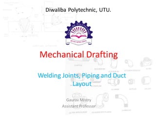
  • 1. Mechanical Drafting Welding Joints, Piping and Duct Layout Gaurav Mistry AssistantProfessor Diwaliba Polytechnic, UTU.
  • 2. Gaurav Mistry 2  Welded Joints MechanicalDrafting Welding  For joining metal parts permanently, welding is used in Engineering Field.  Welding is an effective method of making permanent joints between two or more metal parts.  Cast iron, steel and its alloys, brass and copper are the metals that may be welded easily.  Production of leak proof joints that can withstand high pressures and temperatures are made possible with advanced welding technology.  For this reason, welding is fast replacing casting and forging wherever possible.  When compared to riveting, welding is cheaper, stronger and simpler to execute at site with considerable freedom in design. Hence, it is widely used in ship building and structuralfabrication in place of riveting.  There are different types of welding. It is necessary to have the information regarding the type and size of weld that should be used to carry out required welding work.
  • 3. Gaurav Mistry 3  Welded Joints MechanicalDrafting Advantages and Disadvantages of Welding joint over Rivet joint.
  • 4. Gaurav Mistry 4  Welded Joints MechanicalDrafting  Types of Weld joints. 1. Lap or FilletJoint. The lap joint or the fillet joint is obtained by overlapping the plates and then welding the edges of the plates. The cross-section of the fillet is approximatelytriangular. A single transverse fillet joint has the disadvantage that the edge of the plate which is not welded can buckle or warp out of shape.
  • 5. Gaurav Mistry 5  Welded Joints MechanicalDrafting  Types of Weld joints. 2. Butt Joint. The butt joint is obtainedby placing the platesedge to edge as shown in Fig. In butt welds, the plate edges do not require bevelling if the thickness of plate is less than 5 mm. On the other hand, if the plate thickness is 5 mm to 12.5 mm, the edges should be bevelled to V or U-groove on both sides.
  • 6. Gaurav Mistry 6  Welded Joints MechanicalDrafting  Types of Weld joints. 3. OtherTypes of Weld. The othertype of welded joints are corner joint, edge joint and T-joint. The main considerations involvedin the selectionof weld type are: 1. The shape of the welded component required, 2. The thickness of the plates to be welded, and 3. The direction of the forces applied.
  • 7. Gaurav Mistry 7 MechanicalDrafting  Welded Joints Weld Nomenclature
  • 8. Gaurav Mistry 8 MechanicalDrafting  Welded Joints Standard location of Welding Symbol used to show complete info. in drawing. Elements of a Welding Symbol A welding symbol consists of the following eight elements: 1. Reference line, 2. Arrow, 3. Basic weld symbols, 4. Dimensions and other data, 5. Supplementary symbols, 6. Finish symbols, 7. Tail, and 8. Specification, process or other references.
  • 9. Gaurav Mistry 9 MechanicalDrafting  Welded Joints Designation of welding processes in welding symbol
  • 10. Gaurav Mistry 10 MechanicalDrafting  Welded Joints (i) An arrow line (1) per joint, (ii) A dual reference line, consisting of two parallel lines; one continuous and one dashed (2a, 2b) and (iii) A certain number of dimensions (4) and conventional signs (3). In addition to the weld symbol of the joint to be made, the two conventional signs used for welding as per BIS are (1) A circle at the elbow connecting the arrow and the reference line to indicate welding all around and, (2) (2) A filled-in circle at the elbow indicate welding on site, as shown in Fig
  • 11. Gaurav Mistry 11 MechanicalDrafting  Welded Joints  Elementary/Basic welding symbols
  • 12. Gaurav Mistry 12 MechanicalDrafting  Welded Joints  Elementary/Basic welding symbols
  • 13. Gaurav Mistry 13 MechanicalDrafting  Welded Joints  Elementary/Basic welding symbols
  • 14. Gaurav Mistry 14 MechanicalDrafting  Welded Joints  Supplementary welding symbols
  • 15. Gaurav Mistry 15 MechanicalDrafting  Welded Joints  Combination of Basic and Supplementary welding symbols
  • 16. Gaurav Mistry 16 MechanicalDrafting  Welded Joints  Some Examples showing Representation of Welding symbols
  • 17. Gaurav Mistry 17 MechanicalDrafting  Welded Joints  Methods to show the weld by arrow. (arrow side and other side)
  • 18. Gaurav Mistry 18 MechanicalDrafting  Welded Joints  Welding symbol in relation to the reference line.
  • 19. Gaurav Mistry 19 MechanicalDrafting  Welded Joints  Welding symbol shown by an arrow.
  • 20. Gaurav Mistry 20 MechanicalDrafting  Welded Joints  Dimensions of Weld.
  • 21. Gaurav Mistry 21 MechanicalDrafting  Welded Joints  Illustration to give meaning of Weld symbol.
  • 22. Gaurav Mistry 22 MechanicalDrafting  Piping  Pipe Types and Symbols of pipelines carrying different fluids Pipe Types: 1. Steel Tubes 2. Steel Pipes 3. Cast iron pipes 4. Brass Pipes 5. Copper Pipes 6. Lead Pipes 7. Brass Tubes 8. Aluminium Pipes 9. AluminiumAlloy Pipes 10.Copper AlloyPipes 11.Low Pressure Pipes 12.High Pressure Pipes 13.Drawn Pipes 14.Fabricated Pipes
  • 23. Gaurav Mistry 23 MechanicalDrafting  Piping  Pipe Fittings
  • 24. Gaurav Mistry 24 MechanicalDrafting  Piping  Pipe Fittings
  • 25. Gaurav Mistry 25 MechanicalDrafting  Piping  Pipe FittingsApplications: Applications: 1. Nipple:To increase the length of pipe line. 2. Elbow 90/45 deg: To bend the piping at an angle of 90/45deg. 3. Elbow – reducer: To join the smaller pipe at right angle to the bigger pipe. 4. Reducer tee: To join the small branch pipe with the larger pipe. 5. Coupling:To join two pipes of equal diameter in a straight line. 6. Union: To join the pipes creating the facility of replacing the pipe if required to do so at the time of maintenance. 7. Plug: To close the pipe end having internal threads. 8. Cap: To close the pipe end having external threads. 9. Bend: To give bend to pipe at an angle of 90 deg or more.
  • 26. Gaurav Mistry 26 MechanicalDrafting  Piping  Standard symbols for flanged and threaded pipe fittings and valves
  • 27. Gaurav Mistry 27 MechanicalDrafting  Piping  Line diagram of piping drawing
  • 28. Gaurav Mistry 28 MechanicalDrafting  Piping  Scale layout of piping drawing
  • 29. Gaurav Mistry 29 MechanicalDrafting  Piping  Line diagram of above (scale layout) piping drawing
  • 30. Gaurav Mistry 30 MechanicalDrafting  Duct Layout  Types of Duct and its application  Types of ducts are as under: 1. Ducts with threadedjoints 2. Ducts with flanged joints 3. Welded ducts  Application of ducts: 1. In water supplyservice. 2. In water line, casing line and line pipes in industries. 3. In refinery service. 4. In boilers and superheaters. 5. As a pressure duct. 6. Low and high temperature applications. 7. In pipe line of water wells. 8. In automobilefor radiator pipe lines and in fuel lines. 9. In heat exchangers and condensers. 10. In refrigerators and air conditioners.
  • 31. Gaurav Mistry 31 MechanicalDrafting  Duct Layout  Flanged type fabricated bends.
  • 32. Gaurav Mistry 32 MechanicalDrafting  Duct Layout  Welded type fabricated bends.
  • 33. Gaurav Mistry 33 REFERENCES: 1. Machine Drawing, K. L. Narayan, NewAge Int. Pub. 2. Mechanical Drafting, S. V. Gosai, Atul Prakashan. 3. A text book of Machine Design, R. S. Khurmi, S. Chand Pub. MechanicalDrafting