Pipe Fittings and Valves for Marine Use
•
182 j'aime•12,956 vues

Pipe Fittings and Valves for Marine Use by Mohd. Hanif Dewan, Senior Engg. Lecturer, International Maritime Academy, Bangladesh

Recommandé
Contenu connexe
Tendances
Tendances (20)
Similaire à Pipe Fittings and Valves for Marine Use
Similaire à Pipe Fittings and Valves for Marine Use (20)
Plus de Mohammud Hanif Dewan M.Phil.
Plus de Mohammud Hanif Dewan M.Phil. (20)
Dernier
Dernier (20)
Pipe Fittings and Valves for Marine Use
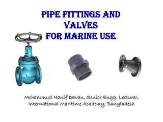
- 1. Pipe Fittings and Valves for Marine Use Mohammud Hanif Dewan, Senior Engg. Lecturer, International Maritime Academy, Bangladesh
- 2. Various Pipe Fittings 4/12/2014 Mohd. Hanif Dewan, Senior Lecturer, International Maritime Academy, Bangladesh. 2
- 3. Nipple: A Pipe Nipple is a short pipe (12 inches or less), with small opening which provides way for the liquids or gases to pass through the pipe. It has a male thread on each end and is used for extension from a fitting. Some of the popular usages of Pipe Nipple are : Used in fluid application to connect two FPT fittings. Used in plumbing system or for ceiling and wall supports and extensions. Used for ceiling or wall supports. Used to extend shower riser. We saw different types of nipples in our fluid mechanics lab. These are: 1. Barrel nipple 2. Hexagonal nipple Barrel Nipple: Applications: Male Pipe to Male Pipe connections Hexagonal Nipple: Applications: Male Pipe to Male Pipe connections 4/12/2014 Mohd. Hanif Dewan, Senior Lecturer, International Maritime Academy, Bangladesh. 3 Fig: Barrel Nipple Fig: Hexagonal Nipple
- 4. Elbow: A pipe fitting installed between two lengths of pipe or tube allowing a change of direction, usually 90° or 45°. The ends may be machined for butt welding, threaded (usually female), or socketed, etc. When the two ends differ in size, it is called a reducing or reducer elbow. Most elbows are available in short radius or long radius of types. We saw different types of elbows in our fluid mechanics lab. These are: 1. 90 degree elbow 2. 45 degree elbow 3. Male female elbow 4. Equal elbow 4/12/2014 Mohd. Hanif Dewan, Senior Lecturer, International Maritime Academy, Bangladesh. 4
- 5. (1) 90 degree elbow: 90 degree elbow, also called "90 bends or 90 ells", are manufactured as SR (Short Radius) elbows and LR (Long Radius) elbows. Applications: The main application area of an elbow (90 degree) is to connect hoses to valves, water pressure pumps, and deck drains. These elbows can be made from tough nylon material or NPT thread. Fig: 90° Elbow4/12/2014 Mohd. Hanif Dewan, Senior Lecturer, International Maritime Academy, Bangladesh. 5
- 6. (2) 45 degree elbow: 45 degree elbow, also called "45 bends or 45 ells" are typically made as LR (Long Radius) elbows. Available in various sizes (in mm or inches), 45 degree pipe elbow is available with different male to female BSP thread connections. Fig: 45° Elbow 4/12/2014 Mohd. Hanif Dewan, Senior Lecturer, International Maritime Academy, Bangladesh. 6
- 7. Male female elbow and connectors: Application of Male Female Connector and elbow Male Female connectors and elbow are put to use in marine and other industries depending on their specifications and internal and external diameter. Fig: Male & Female Elbow 4/12/2014 Mohd. Hanif Dewan, Senior Lecturer, International Maritime Academy, Bangladesh. 7
- 8. (4) Equal elbow: Equal elbows are quick-connect fittings that are extremely helpful in routing water lines that are laid in confined areas. They are known as 'elbow fittings' because they display an angular bent so that two pipes can be easily fixed in the same manner. 4/12/2014 Mohd. Hanif Dewan, Senior Lecturer, International Maritime Academy, Bangladesh. 8
- 9. Union Cross: Union cross is essentially used for piping of tube to tube industrial fittings and connect fractional tubes. These metal fittings offer high mechanical connections for vacuum applications and positive pressure in tube to tube piping systems. Union cross are so designed, that they can be used with orbital weld equipment, these unique fittings have enhanced surface to prevent out gassing and prevent corrosion. These widely used tube fittings allow smooth flow paths and prevent any kind of turbulence or entrapments. These tubing connections eliminate costly, hazardous leaks in instrumentation and process tubing and are available in metric and inches specifications according to various applications. 4/12/2014 Mohd. Hanif Dewan, Senior Lecturer, International Maritime Academy, Bangladesh. 9
- 10. Union and Socket: A union is similar to a coupling, except it is designed to allow quick and convenient disconnection of pipes for maintenance or fixture replacement. While a coupling would require either solvent welding or being able to rotate all the pipes adjacent as with a threaded coupling, a union provides a simple nut transition, allowing easy release at any time. We saw different types of unions in our fluid mechanics lab. These are: 1. Male female union 2. Union joint An opening in any fitting that matches the outside diameter of a pipe or tube, with a further recessed through opening matching the inside diameter of the same pipe or tube. We saw different types of unions in our fluid mechanics lab. These are: 1. Half socket 2. Co-centric reducing socket 4/12/2014 Mohd. Hanif Dewan, Senior Lecturer, International Maritime Academy, Bangladesh. 10
- 11. Fig: Male union fig: Female Union Fig: Half Fig: Concentric Reducing Socket 4/12/2014 Mohd. Hanif Dewan, Senior Lecturer, International Maritime Academy, Bangladesh. 11
- 12. Reducer: A reducer normally refers to a fitting that is used to reduce the diameter of the suction piping to fit the pump intake. It is thus used to join two pipes of different sizes. Reducer is available in both eccentric and concentric designs. Concentric or eccentric reducers are used to properly reduce into and out of circulating pumps. The various advantages include keeping big pipes and small pipes together as well as reducing noise and vibration at the same time. Applications: In Marine and some other industries where they find application are oil, gas, petrochemical, onshore and offshore sectors. They are used in both cargo loading, discharging and transfers operations and vapor recovery/return systems. Reducers for vapor recovery include a pin on one flange and vapor hole on the opposite flange. Concentric reducer save installation space and reduce costs. Piping systems must be anchored when using concentric reducer. 4/12/2014 Mohd. Hanif Dewan, Senior Lecturer, International Maritime Academy, Bangladesh. 12
- 13. 4/12/2014 Mohd. Hanif Dewan, Senior Lecturer, International Maritime Academy, Bangladesh. 13
- 14. Equal Tee: A tee is amongst the most common pipe fittings and is available with all female thread sockets, all solvent weld sockets, or with opposed solvent weld sockets and a side outlet with female threads. This is a T- shaped device which has three openings that act as an outlet for the pipe. Applications: A tee is used for connecting pipes of different diameters or for changing the direction of pipe runs. Figure: Tee 4/12/2014 Mohd. Hanif Dewan, Senior Lecturer, International Maritime Academy, Bangladesh. 14
- 15. Long and Short bend: Applications: Use for small and large pipe connections between pipes. Fig: Long bend fig: Short bend 4/12/2014 Mohd. Hanif Dewan, Senior Lecturer, International Maritime Academy, Bangladesh. 15
- 16. GASKET A gasket is a mechanical seal that fills the space between two objects, generally to prevent leakage between the two objects while under compression. Gaskets save money by allowing "less- than-perfect" mating surfaces on machine parts which can use a gasket to fill irregularities. Gaskets are commonly produced by cutting from sheet materials, such as gasket paper, rubber, silicon, metal, cork, fiberglass or a plastic polymer. Gaskets for specific aplications may contain asbestos. It is usually desirable that the gasket be made from a material that is to some degree yielding such that it is able to deform and tightly fills the space it is designed for, including any slight irregularities. Many gaskets require an application of sealant directly to the gasket surface to function properly. 4/12/2014 Mohd. Hanif Dewan, Senior Lecturer, International Maritime Academy, Bangladesh. 16
- 17. Various Types of Gaskets 4/12/2014 Mohd. Hanif Dewan, Senior Lecturer, International Maritime Academy, Bangladesh. 17
- 18. Various Valves 4/12/2014 Mohd. Hanif Dewan, Senior Lecturer, International Maritime Academy, Bangladesh. 18
- 19. Valve: a valve is a mechanical device that controls the flow of fluid and pressure within a system or process. a valve controls system or process fluid flow and pressure by performing any of the following functions: i. stopping and starting fluid flow ii. varying (throttling) the amount of fluid flow iii. controlling the direction of fluid flow iv. regulating downstream system or process pressure v. relieving component or piping over pressure 4/12/2014 Mohd. Hanif Dewan, Senior Lecturer, International Maritime Academy, Bangladesh. 19
- 20. STOP ( ISOLATION ) VALVES: 4/12/2014 Mohd. Hanif Dewan, Senior Lecturer, International Maritime Academy, Bangladesh. 20
- 21. REGULATING VALVES 4/12/2014 Mohd. Hanif Dewan, Senior Lecturer, International Maritime Academy, Bangladesh. 21
- 22. BACK FLOW PREVENTION VALVES 4/12/2014 Mohd. Hanif Dewan, Senior Lecturer, International Maritime Academy, Bangladesh. 22
- 23. PRESSURE RELIEF-VALVE 4/12/2014 Mohd. Hanif Dewan, Senior Lecturer, International Maritime Academy, Bangladesh. 23
- 24. TYPES OF VALVES 4/12/2014 Mohd. Hanif Dewan, Senior Lecturer, International Maritime Academy, Bangladesh. 24 1. GATE VALVES 2. GLOBE VALVES 3. PLUG VALVES 4. DIAPHRAGM VALVES 5. BALL VALVES 6. BUTTERFLY VALVES 7. NEEDLE VALVES 8. CHECK VALVES 9. PRESSURE RELIEF VALVES 10. CONTROL VALVES
- 25. Gate Valves 4/12/2014 Mohd. Hanif Dewan, Senior Lecturer, International Maritime Academy, Bangladesh. 25
- 26. Gate valve. 26
- 27. Gate Valve A gate valve is a linear motion valve used to start or stop fluid flow; however, it does not regulate or throttle flow. The name gate is derived from the appearance of the disk in the flow stream. The disk of a gate valve is completely removed from the flow stream when the valve is fully open. This characteristic offers virtually no resistance to flow when the valve is open. Hence, there is little pressure drop across an open gate valve. When the valve is fully closed, a disk-to-seal ring contact surface exists for 360°, and good sealing is provided. With the proper mating of a disk to the seal ring, very little or no leakage occurs across the disk when the gate valve is closed. On opening the gate valve, the flow path is enlarged in a highly nonlinear manner with respect to percent of opening. This means that flow rate does not change evenly with stem travel. 4/12/2014 Mohd. Hanif Dewan, Senior Lecturer, International Maritime Academy, Bangladesh. 27
- 28. Also, a partially open gate disk tends to vibrate from the fluid flow. Most of the flow change occurs near shutoff with a relatively high fluid velocity causing disk and seat wear and eventual leakage if used to regulate flow. For these reasons, gate valves are not used to regulate or throttle flow. A gate valve can be used for a wide variety of fluids and provides a tight seal when closed. The major disadvantages to the use of a gate valve are: - It is not suitable for throttling applications. - It is prone to vibration in the partially open state. - It is more subject to seat and disk wear than a globe valve. - Repairs, such as lapping and grinding, are generally more difficult to accomplish. 4/12/2014 Mohd. Hanif Dewan, Senior Lecturer, International Maritime Academy, Bangladesh. 28
- 29. Gate Valve 29 ON – Off Valve ,Used in: 1-Water. 2- Oil. 3- Gas 4- Steam and 5- Other Fluid Services.
- 30. Wedge gate valve and parallel slide valve 30
- 31. Gate valve 31
- 32. TYPES OF GATE VALVES – RISING STEM GATE VALVE 4/12/2014 Mohd. Hanif Dewan, Senior Lecturer, International Maritime Academy, Bangladesh. 32
- 33. TYPES OF GATE VALVES – NON RISING STEM GATE VALVE 4/12/2014 Mohd. Hanif Dewan, Senior Lecturer, International Maritime Academy, Bangladesh. 33
- 34. Globe Valves 4/12/2014 Mohd. Hanif Dewan, Senior Lecturer, International Maritime Academy, Bangladesh. 34
- 35. Globe Valve (High Pressure Value ) 35
- 36. Globe Valve 36
- 37. Globe Valve 37
- 38. GLOBE VALVE A globe valve, different from ball valve, is a type of valve used for regulating flow in a pipeline, consisting of a movable disk-type element and a stationary ring seat in a generally spherical body. Globe valves are named for their spherical body shape with the two halves of the body being separated by an internal baffle. This has an opening that forms a seat onto which a movable plug can be screwed in to close (or shut) the valve. The plug is also called a disc or disk. In globe valves, the plug is connected to a stem which is operated by screw action using a handwheel in manual valves. Typically, automated globe valves use smooth stems rather than threaded and are opened and closed by an actuator assembly. 4/12/2014 Mohd. Hanif Dewan, Senior Lecturer, International Maritime Academy, Bangladesh. 38
- 39. TYPES OF GLOBE VALVE – TEE PATTERN GLOBE VALVES 4/12/2014 Mohd. Hanif Dewan, Senior Lecturer, International Maritime Academy, Bangladesh. 39
- 40. TYPES OF GLOBE VALVE – ANGLE PATTERN GLOBE VALVES 4/12/2014 Mohd. Hanif Dewan, Senior Lecturer, International Maritime Academy, Bangladesh. 40
- 41. Plug Valves 4/12/2014 Mohd. Hanif Dewan, Senior Lecturer, International Maritime Academy, Bangladesh. 41
- 42. PLUG VALVES 4/12/2014 Mohd. Hanif Dewan, Senior Lecturer, International Maritime Academy, Bangladesh. 42
- 43. Plug valve (on-off) or Cock (low-pressure) 43
- 44. Plug valve (on-off) or Cock 44
- 45. Plug valve Applications 45 Gas and liquid fuel Water. Extreme temperature flow Boiler feed water. Low Pressure Steam . Corrosive Liquids and Gases
- 46. Diaphargm Valves 4/12/2014 Mohd. Hanif Dewan, Senior Lecturer, International Maritime Academy, Bangladesh. 46
- 47. DIAPHRAGM VALVES 4/12/2014 Mohd. Hanif Dewan, Senior Lecturer, International Maritime Academy, Bangladesh. 47
- 48. Ball Valves 4/12/2014 Mohd. Hanif Dewan, Senior Lecturer, International Maritime Academy, Bangladesh. 48
- 49. Ball Valve A ball valve is a rotational motion valve that uses a ball-shaped disk to stop or start fluid flow. The ball, shown in Figure 12, performs the same function as the disk in the globe valve. When the valve handle is turned to open the valve, the ball rotates to a point where the hole through the ball is in line with the valve body inlet and outlet. When the valve is shut, the ball is rotated so that the hole is perpendicular to the flow openings of the valve body and the flow is stopped. Most ball valve actuators are of the quick-acting type, which require a 90° turn of the valve handle to operate the valve. Other ball valve actuators are planetary gear-operated. This type of gearing allows the use of a relatively small handwheel and operating force to operate a fairly large valve. Some ball valves have been developed with a spherical surface coated plug that is off to one side in the open position and rotates into the flow passage until it blocks the flowpath completely. Seating is accomplished by the eccentric movement of the plug. The valve requires no lubrication and can be used for throttling service. 4/12/2014 Mohd. Hanif Dewan, Senior Lecturer, International Maritime Academy, Bangladesh. 49
- 50. Advantages A ball valve is generally the least expensive of any valve configuration and has low maintenance costs. In addition to quick, quarter turn on-off operation, ball valves are compact, require no lubrication, and give tight sealing with low torque. Disadvantages Conventional ball valves have relatively poor throttling characteristics. In a throttling position, the partially exposed seat rapidly erodes because of the impingement of high velocity flow. 4/12/2014 Mohd. Hanif Dewan, Senior Lecturer, International Maritime Academy, Bangladesh. 50
- 51. TYPES OF BALL VALVES – FLANGED END BALL VALVES 4/12/2014 Mohd. Hanif Dewan, Senior Lecturer, International Maritime Academy, Bangladesh. 51
- 52. TYPES OF BALL VALVES – SCREWED END BALL VALVES 4/12/2014 Mohd. Hanif Dewan, Senior Lecturer, International Maritime Academy, Bangladesh. 52
- 53. Check Valves 4/12/2014 Mohd. Hanif Dewan, Senior Lecturer, International Maritime Academy, Bangladesh. 53
- 54. Check Valve Check valves are designed to prevent the reversal of flow in a piping system. These valves are activated by the flowing material in the pipeline. The pressure of the fluid passing through the system opens the valve, while any reversal of flow will close the valve. Closure is accomplished by the weight of the check mechanism, by back pressure, by a spring, or by a combination of these means. 4/12/2014 Mohd. Hanif Dewan, Senior Lecturer, International Maritime Academy, Bangladesh. 54
- 55. TYPES OF CHECK VALVES – BALL CHECK VALVES 4/12/2014 Mohd. Hanif Dewan, Senior Lecturer, International Maritime Academy, Bangladesh. 55
- 56. Ball Valves 4/12/2014 Mohd. Hanif Dewan, Senior Lecturer, International Maritime Academy, Bangladesh. 56
- 57. Ball check valve (for heavy fluids) installed horizontal ,vertical & angle 57
- 59. TYPES OF CHECK VALVES – SWING CHECK VALVES 4/12/2014 Mohd. Hanif Dewan, Senior Lecturer, International Maritime Academy, Bangladesh. 59
- 60. TYPES OF CHECK VALVES – LIFT CHECK VALVES 4/12/2014 Mohd. Hanif Dewan, Senior Lecturer, International Maritime Academy, Bangladesh. 60
- 62. Split disc check valve operation 62
- 63. lift check valve (Recommended for Vapor service) 63
- 64. Swing check valve (liquids) installed horizontal & vertical 64
- 65. Swing check valve Ops. 65
- 67. 29 check valves
- 68. Butterfly Valves 4/12/2014 Mohd. Hanif Dewan, Senior Lecturer, International Maritime Academy, Bangladesh. 68
- 69. Butterfly Valves A butterfly valve, illustrated in Figure 19, is a rotary motion valve that is used to stop, regulate, and start fluid flow. Butterfly valves are easily and quickly operated because a 90o rotation of the handle moves the disk from a fully closed to fully opened position. Larger butterfly valves are actuated by handwheels connected to the stem through gears that provide mechanical advantage at the expense of speed. Butterfly valves possess many advantages over gate, globe, plug, and ball valves, especially for large valve applications. Savings in weight, space, and cost are the most obvious advantages. The maintenance costs are usually low because there are a minimal number of moving parts and there are no pockets to trap fluids. Butterfly valves are especially well-suited for the handling of large flows of liquids or gases at relatively low pressures and for the handling of slurries or liquids with large amounts of suspended solids. Butterfly valves are built on the principle of a pipe damper. The flow control element is a disk of approximately the same diameter as the inside diameter of the adjoining pipe, which rotates on either a vertical or horizontal axis. When the disk lies parallel to the piping run, the valve is fully opened. When the disk approaches the perpendicular position, the valve is shut. Intermediate positions, for throttling purposes, can be secured in place by handle-locking devices. 4/12/2014 Mohd. Hanif Dewan, Senior Lecturer, International Maritime Academy, Bangladesh. 69
- 70. 19 Butterfly Valve Flow Control Low Speed Both Side flow
- 71. Butterfly Valve A Butterfly Valve is used for isolating or regulating flow. The Closing mechanism takes the form of a disk. Operation is similar to that of a ball valve, which allows for quick shut off. Butterfly valves are generally lower in cost , lighter in weight and meaning less support is required.
- 72. 72
- 74. TYPES OF BUTTERFLY VALVES – FLANGED-END BUTTERFLY VALVES 4/12/2014 Mohd. Hanif Dewan, Senior Lecturer, International Maritime Academy, Bangladesh. 74
- 75. TYPES OF BUTTERFLY VALVES – FLANGED-END BUTTERFLY VALVES 4/12/2014 Mohd. Hanif Dewan, Senior Lecturer, International Maritime Academy, Bangladesh. 75
- 76. Needle Valves 4/12/2014 Mohd. Hanif Dewan, Senior Lecturer, International Maritime Academy, Bangladesh. 76
- 77. Needle Valves A needle valve, as shown in Figure 20, is used to make relatively fine adjustments in the amount of fluid flow. The distinguishing characteristic of a needle valve is the long, tapered, needlelike point on the end of the valve stem. This "needle" acts as a disk. The longer part of the needle is smaller than the orifice in the valve seat and passes through the orifice before the needle seats. This arrangement permits a very gradual increase or decrease in the size of the opening. Needle valves are often used as component parts of other, more complicated valves. For example, they are used in some types of reducing valves. Needle Valve Applications Most constant pressure pump governors have needle valves to minimize the effects of fluctuations in pump discharge pressure. Needle valves are also used in some components of automatic combustion control systems where very precise flow regulation is necessary 4/12/2014 Mohd. Hanif Dewan, Senior Lecturer, International Maritime Academy, Bangladesh. 77
- 78. 18 Needle Valve Fine accurate flow Cont.
- 79. NEEDLE VALVES 4/12/2014 Mohd. Hanif Dewan, Senior Lecturer, International Maritime Academy, Bangladesh. 79
- 80. Pressure Relief Valves (Relief Valve & Safety Valve) 4/12/2014 Mohd. Hanif Dewan, Senior Lecturer, International Maritime Academy, Bangladesh. 80
- 81. Relief and Safety Valves Relief and safety valves prevent equipment damage by relieving accidental over-pressurization of fluid systems. The main difference between a relief valve and a safety valve is the extent of opening at the setpoint pressure. A relief valve, illustrated in Figure 28, gradually opens as the inlet pressure increases above the setpoint. A relief valve opens only as necessary to relieve the over-pressure condition. A safety valve, illustrated in Figure 29, rapidly pops fully open as soon as the pressure setting is reached. A safety valve will stay fully open until the pressure drops below a reset pressure. The reset pressure is lower than the actuating pressure setpoint. The difference between the actuating pressure setpoint and the pressure at which the safety valve resets is called blowdown. Blowdown is expressed as a percentage of the actuating pressure setpoint. 4/12/2014 Mohd. Hanif Dewan, Senior Lecturer, International Maritime Academy, Bangladesh. 81
- 82. Relief valves are typically used for incompressible fluids such as water or oil. Safety valves are typically used for compressible fluids such as steam or other gases. Safety valves can often be distinguished by the presence of an external lever at the top of the valve body, which is used as an operational check. As indicated in Figure 29, system pressure provides a force that is attempting to push the disk of the safety valve off its seat. Spring pressure on the stem is forcing the disk onto the seat. At the pressure determined by spring compression, system pressure overcomes spring pressure and the relief valve opens. As system pressure is relieved, the valve closes when spring pressure again overcomes system pressure. Most relief and safety valves open against the force of a compression spring. The pressure setpoint is adjusted by turning the adjusting nuts on top of the yoke to increase or decrease the spring compression. 4/12/2014 82
- 83. safety valves and relief valves 83 Safety valves are primarily used with compressible gases and in particular for steam and air services . Relief valves are commonly used in liquid systems
- 84. Pressure Relief Valves 84 Releases excess pressure to protect system. Use with Gases & Vapors & liquid. Open Full at once at set pressure. Outlet port larger than inlet port. Never adjust whilst in service.
- 85. TYPES OF PRESSURE RELIEF VALVE – SAFETY VALVE 4/12/2014 Mohd. Hanif Dewan, Senior Lecturer, International Maritime Academy, Bangladesh. 85
- 86. TYPES OF PRESSURE RELIEF VALVE – RELIEF VALVE 4/12/2014 Mohd. Hanif Dewan, Senior Lecturer, International Maritime Academy, Bangladesh. 86
- 87. Type of Pressure Relief Valve 87 Safety valve :Used with compressible gases .steam and air services . Relief valve : Used in liquid systems. as pressure overspill devices . Safety relief valve : used either for liquid or compressible fluid.
- 88. Pressure Relieve valve (safety valve) for clean air Releases excess pressure (clean air) 88
- 89. Safety valve - liquid applications, opens in proportion to the 89
- 90. Typical examples of safety valves used on steam & Air systems 90
- 91. 39
- 92. Control System & Control Valves 4/12/2014 Mohd. Hanif Dewan, Senior Lecturer, International Maritime Academy, Bangladesh. 92
- 94. Control system would normally consist of the following components: Control valves. Actuators. Controllers. Sensors. 94
- 95. 43
- 96. CONTROL VALVES 4/12/2014 Mohd. Hanif Dewan, Senior Lecturer, International Maritime Academy, Bangladesh. 96
- 97. Control Valves Control Valves are valves used to control conditions such as flow, Pressure, Temperature and level by fully or partially opening or closing in response to signals received from controllers that compare a set point to a process variable. Control Valve belongs to the category of Final Control Element.
- 98. The Major three elements of Control Valve: 1. Valve Body 2. Actuator 3. Bonnet Assembly
- 99. Control Valve Accessories • Positioner • I/P Converter • Limit Switch • Solenoid Valve • Air Filter Regulator • Pneumatic Lock up system
- 100. Solenoid Valve A solenoid valve is an electromechanical device used for controlling liquid or gas flow. The solenoid valve is controlled by electrical current , which is run through a coil. When the coil is energized, a magnetic field is created, causing a plunger inside the coil to move. Depending on the design of the valve, the plunger will either open or close the valve. When electrical current is removed form the coil, the valve will return to its de- energized state.
- 101. Valve positions 10 1
- 102. Orifice plate 10 2
- 103. Steam Traps 4/12/2014 Mohd. Hanif Dewan, Senior Lecturer, International Maritime Academy, Bangladesh. 103
- 104. TYPES OF STEAM TRAPS – FLOAT STEAM TRAP 4/12/2014 Mohd. Hanif Dewan, Senior Lecturer, International Maritime Academy, Bangladesh. 104
- 105. TYPES OF STEAM TRAPS –THERMOSTATIC STEAM TRAP 4/12/2014 Mohd. Hanif Dewan, Senior Lecturer, International Maritime Academy, Bangladesh. 105
- 106. TYPES OF STEAM TRAPS –THERMODYNAMIC STEAM TRAP 4/12/2014 Mohd. Hanif Dewan, Senior Lecturer, International Maritime Academy, Bangladesh. 106
- 107. TYPES OF STEAM TRAPS – INVERTED BUCK STEAM TRAP 4/12/2014 Mohd. Hanif Dewan, Senior Lecturer, International Maritime Academy, Bangladesh. 107
- 108. Strainers and Filters 4/12/2014 Mohd. Hanif Dewan, Senior Lecturer, International Maritime Academy, Bangladesh. 108
- 109. TYPES OF STRAINERS – WYE STRAINER 4/12/2014 Mohd. Hanif Dewan, Senior Lecturer, International Maritime Academy, Bangladesh. 109
- 110. TYPES OF STRAINERS – BASKET STRAINER 4/12/2014 Mohd. Hanif Dewan, Senior Lecturer, International Maritime Academy, Bangladesh. 110
- 111. Strainers & Filters 4/12/2014 Mohd. Hanif Dewan, Senior Lecturer, International Maritime Academy, Bangladesh. 111
- 112. Any Question? Thank You! 4/12/2014 Mohd. Hanif Dewan, Senior Lecturer, International Maritime Academy, Bangladesh. 112