

Recommandé
Contenu connexe
Tendances
Tendances (20)
Similaire à Suspension Design casestudy
Similaire à Suspension Design casestudy (20)
Dernier
Dernier (20)
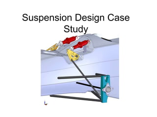
Suspension Design casestudy
- 2. Purpose • Suspension to be used on a small (lightweight) formula style racecar. • Car is intended to navigate tight road courses • Surface conditions are expected to be relatively smooth
- 3. Performance Design Parameters • For this case the main objective is to optimize mechanical grip from the tire. • This is achieved by considering as much tire information as possible while designing the suspension • Specific vehicle characteristics will be considered.
- 4. Considerations • Initially the amount of suspension travel that will be necessary for this application must be considered. – One thing that is often overlooked in a four wheeled vehicle suspension design is droop travel. • Depending on the expected body roll the designer must allow adequate droop travel.
- 5. Introduction
- 6. Components • Upper A-arm – The upper A-arm serves to carry some of the load generated on the suspension by the tire. – This force is considerably less then the load carried by the lower A-arm in a push rod set-up – The arm only has to provide a restoring force to the moment generated by the tire on the lower ball joint
- 7. Components • Lower A-arm – The lower A-arm serves the same purpose as the upper arm, except that in a pushrod configuration it is responsible for carrying the vertical load – In this case study the lower A-arm will carry a larger rod end to compensate for the larger forces seen by this component.
- 8. Components • Upright – The upright serves several purposes in the suspension • Connects the upper A- arm, lower A-arm, steering arm, and the tire • Carries the spindle and bearing assembly • Holds the brake caliper in correct orientation with the rotor • Provides a means for camber and castor adjustment
- 9. Components • Spindle – Spindle can come in two basic configurations • Live spindle • Fixed spindle – In the live spindle configuration the whole spindle assembly rotates and carries the tire and wheel – The fixed spindle configuration carries a hub assembly which rotates about the spindle – Both configurations carry the brake rotor
- 10. Live Vs. Fixed Spindle Advantages and Disadvantages • Live Spindle : – Less parts – Lighter weight if designed correctly – More wheel offset – Bearing concerns – Retention inside of the upright assembly • Fixed spindle – Simple construction – Hub sub-assembly – Spindle put in considerable bending – More components, and heavier
- 11. Components • Push rod – The push rod carries the load from the lower A-arm to the inboard coil over shock – The major concern with this component is the buckling force induced in the tube
- 12. Components • Toe rod (steering link) – The toe rod serves as a like between the steering rack inboard on the vehicle – The location of the ends of this like are extremely critical to bump steer and Ackermann of the steering system – This link is also used to adjust the amount of toe- out of the wheels
- 13. Components • Bellcrank – This is a common racing description of the lever pivot that translates to motion of the push rod into the coil over shock – The geometry of this pivot can be designed to enable the suspension to have a progressive or digressive nature – This component also offers the designer the ability to include a motion ratio in the suspension
- 14. Components • Coil-over Shock Absorber – This component carries the vehicle corner weight – It is composed of a coil spring and the damper – This component can be used to adjust ride height, dampening, spring rate, and wheel rate
- 15. Components • Anti-Roll bar – This component is an additional spring in the suspension – Purpose: resist body roll – It accomplishes this by coupling the left and right corners of the vehicle – When the vehicle rolls the roll bar forces the vehicle to compress the spring on that specific corner as well as some portion of the opposite corners spring • This proportion is adjusted by changing the spring rate of the bar itself*Unclear in this picture the Anti-Roll bar tube actually passes inside the chassis
- 16. Beginning the Design Process • Initially the suspension should be laid out from a 2-D front view • Static and dynamic camber should be defined during this step
- 17. Camber • The main consideration at this step is the camber change throughout the suspension travel.
- 18. Camber • Static Camber – Describes the camber angle with loaded vehicle not in motion • Dynamic Camber – Describes the camber angle of a corner at any instant during a maneuver i.e.: cornering, launching, braking
- 19. Contact Patch •Tread area in contact with the road at any instant in time
- 20. Camber • Camber is used to offset lateral tire deflection and maximize the tire contact patch area while cornering.
- 21. Camber • Negative Camber angles – good for lateral acceleration, cornering – bad for longitudinal acceleration, launching/braking This is because the direction of the tire deflection is obviously not the same for these two situations
- 22. Camber • Cornering Situation – Maximum lateral grip is needed during cornering situations. • In a cornering situation the car will be rolled to some degree • Meaning the suspension will not be a static position • For this reason static suspension position is much less relevant than the dynamic
- 23. Camber • Launch/Braking Situation – Maximum longitudinal grip is needed during launch/brake situations. • In a launch/brake situation the car will be pitched to some degree • Suspension will not be in a static position
- 24. Compromise • It is apparent that the suspension is likely to be at the same position for some cornering maneuvers as it is during launching/braking maneuvers – For this reason we must compromise between too little and too much negative camber – This can be approximated with tire data and often refined during testing
- 25. Defining Camber • Once we set our static camber we must adjust our dynamic camber curves – This is done by adjusting the lengths of the upper and lower A-arms and the position of the inboard and out board pivots – These lengths and locations are often driven by packaging constraints
- 26. Instant Center • The instant center is a dynamic point which the wheel will pivot about and any instant during the suspension travel – For a double wishbone configuration this point moves as the suspension travels CHASSIS Instant Center
- 27. Mild Camber Change Design -Suspension arms are close to parallel -Wide instant center locations
- 28. Mild Camber Change Design 0.4° of Neg. Camber Gain Per inch of Bump
- 29. Aggressive Camber Change Design -Suspension arms are far from parallel -Instant center locations are inside the track width
- 30. More Aggressive Camber Change Design 1.4° of Neg. Camber Gain Per inch of Bump
- 31. Jacking forces • It is important to consider the Instant Center Position, because when it moves vertically off the ground plane Jacking forces are introduced
- 32. Jacking forces • Caused during cornering by a moment – Force: lateral traction force of tire – Moment arm: Instant Center height – Moment pivot: Instant center CHASSIS Instant Center Lateral Force Ground I.C. Height
- 33. Jacking Forces CHASSIS I. C. Lateral Force I.C. Height – Caused by geometrical binding of the upper and lower A-arms – These forces are transferred from the tire to the chassis by the A-arms, and reduce the amount of force seen by the spring Jacking Forces
- 34. Roll Center • The roll center can be identified from this 2-D front view – Found at the intersection lines drawn for the Instant center to the contact patch center point, and the vehicle center line I. C. Roll Center VehicleCenter Line
- 35. Roll Center • For a parallel-Iink Situation the Roll Center is found on the ground plane Roll Center VehicleCenter Line
- 36. Significance of the Roll Center • Required Roll stiffness of the suspension is determine by the roll moment. Which is dependant on Roll center height Roll Center Sprung Mass C.G.
- 37. Roll Moment • Present during lateral acceleration (the cause of body roll) – Moment Arm: B = Sprung mass C.G. height – Roll center height – Force: F = (Sprung Mass) x (Lateral Acceleration) R. C. Sprung Mass C.G. B
- 38. Roll Axis • To consider the total vehicle you must look at the roll axis Rear Roll Center Front Roll Center Sprung Mass C.G.
- 39. Side View • The next step will be to consider the response of the suspension geometry to pitch situation – For this we will move to a 2-D side-view Inboard A-arm pivot points Ground Front Rear CHASSIS
- 40. Anti-Features • By angling the A-arms from the side jacking forces are created – These forces can be used in the design to provide pitch resistance Ground Front Rear CHASSIS Anti-Dive Anti-Lift
- 41. Anti-Features • Racecars rely heavily on wings and aerodynamics for performance. – Aerodynamically efficient, high-down force cars are very sensitive to pitch changes. – A pitch change can drastically affect the amount of down force being produced. • Much less important for lower speed cars
- 42. Pitch Center Pitch Center • The pitch center can be identified from this 2-D side view – Found at the intersection lines drawn for the Instant center to the contact patch center point
- 43. Pitch Center Pitch Center • The pitch center can be identified from this 2-D side view – Found at the intersection lines drawn for the Instant center to the contact patch center point
- 44. Pitch Moment Pitch Center • Present during longitudinal acceleration – Moment Arm: B = Sprung mass C.G. height – Roll center height – Force: F = (Sprung Mass) x (Longitudinal Acceleration) B F