Film properties tests and details
•Télécharger en tant que DOC, PDF•
30 j'aime•18,065 vues


Recommandé
Contenu connexe
Tendances
Tendances (20)
En vedette
En vedette (15)
Similaire à Film properties tests and details
Similaire à Film properties tests and details (20)
Film properties tests and details
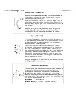
- 1. Film and Package Tests Printable Version (.PDF) Specular Gloss - ASTM-D-1223 Gloss is measured on a glossmeter. This instrument has an incandescent light source and a photosensitive receptor which responds to visible light. Light shines onto the sample at a specified angle. Some of this light is reflected into the photosensitive receptor. The fraction of the original light which is reflected is the gloss of the sample. Gloss is an important merchandising factor and this test makes it possible to specify and control this surface characteristic so that the desired effect will be assured. Haze - ASTM-D-1003 The haze of transparent packaging materials is measured on a special hazemeter which has an incandescent light source and geometrically arranged photocells that measure the transmitted and scattered light. The sample is placed between the light source and the photocells. The amount of light transmitted by the sample, the light scattered by the sample and the instrument and the total incident light are measured. From these values the percentage of transmitted light which is scattered can be calculated. The hazemeter measures these variables and interrelates them so that the percentage of scattered light can be read on the meter. this test is important to products or in uses where true color and high visibility are required. Transmittance - ASTM-D-1003 The percent of light transmission on translucent materials is measured on the same instrument as haze. Using its incandescent light source and geometrically arranged photocells which ratio the amount of light transmitted through the sample versus the amount transmitted with no sample present. Transmittance, Opacity and Optical Density are related mathematically as: Opacity = 1 / Transmittance Optical Density = Common Logarithm (Opacity)
- 2. Tappi Opacity - T-425 Tappi Opacity is a reflectance type of Opacity measurement. It is a contrast ratio obtained by testing the samples reflectance when backed by a black material versus the reflectance when the film is backed by a white material. The incandescent light source and photocell detector are on the same side of the sample while the background is placed behind the sample. Tappi Opacity = Light reflected when sample backed by black background / Light reflected when sample backed by white background Water-Vapor Transmission - ASTM-F372 The water vapor transmission rate (WVTR) through flexible barrier films is measured using an infrared diffusometer. The diffusometer establishes a condition of 90% relative humidity at 100°F on one side of a film by means of a heated saturated salt solution and a condition of 0% relative humidity at 100°F on the other side using a stream of warm dry air. When the source of dry air is turned off, moisture vapor permeating the film from the moist side accumulates on the dry side. The rate at which this moisture build up takes place is sensed by an infrared detector and recorded as WVTR. This test is extremely important since it gives a "baseline" value for comparing films in terms of moisture barrier. However, it should be pointed out that WVTR is normally measured on flat sheets and does not include end use package variables such as heat seals, folds, and creases. Tear-ASTM-D-1922 A tear tester has a stationary clamp and a movable clamp on a pendulum, means for holding this pendulum in a raised position, then quickly releasing it, and a scale that registers the arc through which the released pendulum swings. Samples of paper or film are clamped into the tester and nicked to start the tear; then the pendulum clamp is released. This tears the sample and the scale registers the arc. As the arc is proportional to the tear strength of the sample, calibration of the arc gives the tear strength. Tear strength is reported in grams. It is the force necessary to continue tearing a sample after a nick has been made. This test is very important for all films as well as for paper. High tear values may be needed for machine operations or for package strength. However, low tear values are necessary and useful for easy opening of some package types.
- 3. Tensile and Elongation - ASTM-D-882 The testing machine of clamps to hold the sample, some means of gradually increasing the load on the specimen until it breaks and indicators which show the load and the amount of elongation. To perform the test, measured, gauged specimens are clamped into the testing machine and stretched until they break. Tensile strength is usually reported in pounds per inch of width necessary to pull the paper apart. For films, the usual units are pounds per square inch of original cross-sectional area. Tensile strength is quite literally the amount of force necessary to pull a material apart. The elongation is the amount a material will stretch before breaking. Tensile strength is a most important value for materials used in applications such as heavy-duty bags. A large value for elongation is an index of toughness, since it indicates a material will absorb a large amount of energy before breaking. Gas Transmission Test specimens are clamped in the 100 cm2 diffusion cell. Both sides of the cell are initially purged with an oxygen- free carrier gas to remove residual oxygen from the system and de-sorb oxygen from the sample. When a stable zero reading has been established, oxygen is introduced into the upper half of the diffusion chamber. The carrier gas continues to flow through the lower half and into the coulometric oxygen detector. After a short interval, the first molecules of oxygen diffusing through the barrier are conveyed by the carrier gas to the detector. As displayed by the graphic recorder, the detector current rises, finally leveling off at a value representative of the equilibrium transmission rate of oxygen through the barrier. It should be noted that this equilibrium transmission rate is independent of the flow rate of the carrier gas. Impact Strength - ASTM-D-3420 The pendulum impact tester can be used to measure impact strength of papers, boards and films. An impacting head on the end of a pendulum is swung through an arc into and through sample. Tester has a means of measuring difference between potential energy of pendulum at maximum height in free swing and potential energy of the pendulum after rupture of sample. This difference in energy is defined as impact strength and is reported in units of kilogram-centimeters. It is useful in predicting resistance of a material to breakage from dropping or other quick blows.
- 4. A test similar in scope, method and significance is the dart drop test (ASTM-D-1709). Weighted dart is dropped from standard height onto taut sample. Significance and purpose are the same as in the pendulum test. Dart unit is weight of dart in grams that breaks sample 50% of the time. These tests give an index of material's dynamic strength and approximate what will occur when package is dropped. ***************************************************************************************** * Sealing Film Printable Version (.PDF) Sealing Theory SEAL = HEAT + TIME + PRESSURE The sum total of these three variables should remain constant in order to effect consistent seals. For example, if dwell time is reduced, then heat or pressure may be needed to be increased to compensate. Heat & Time The effort to regulate heat is not as straightforward as simply setting the temperature on a controller to the suggested sealing temperature of a packaging material. Machine speeds effect the temperature of the crimper or sealing jaw face, since heat is constantly being drawn off the face by the packaging material. The heat must also be sufficient to penetrate from the face of the crimper or jaw through the film or lamination to the sealant layer, and not so high that it damages the film or lamination. The more time available for contact between the crimpers and the packaging materials (referred to as dwell time), the more heat can penetrate through to the sealant layer. As production speeds are increased, sealant layer quality and/or quantity may need to be enhanced. Crimpers and sealing jaws can be manufactured from special materials that are especially good at transferring heat. Easy Seal Crimpers utilize a special, durable bronze alloy sealing face, and sealing jaws can also be manufactured with copper bodies and durable Hastelloy sealing faces. Col Seal films remove both heat and time as variables, since all that is required to make a seal is pressure.
- 5. Pressure The variability of pressure can be made constant through refinements in crimper or sealing jaw setup and design. Inadequate or uneven sealing pressure can cause end seal leaks, especially at the intersection of two and four layers of film in areas such as the fin seal, wrinkles or gussets. Sometimes additional heat or dwell time can help sealant to flow into and plug leaks in these areas, but these solutions may not be practical. Attempts to improve seals by increasing sealing pressure can cause the crimpers/jaws to split or cut the package. Setup On all machines the serrations need to be aligned properly. On horizontal wrappers the crimper clearance and spring pressure need to be set properly, and backlash (independent movement of the upper and lower shafts) needs to be controlled. It can take a great deal of skill and finesse to create enough pressure to seal without having excess pressure split or cut the packaging material. If no amount of adjusting allows you to achieve adequate results, then a change in the design of the crimpers or sealing jaws is necessary. Design Design changes can entail an upgrade to Easy Seal Crimpers and/or a change in the serration pattern. Either way, our goal is to provide even sealing pressure across varying layers of film in the end seal area. Serration Patterns It is rare to see crimpers and jaws on horizontal wrappers or vertical baggers with smooth faces; they almost all have some type of serration pattern. As the packaging material is stretched over the serration pattern extra sealing pressure is exerted. The serrations also cause a "shearing" action, where sealant layers from each side are forcibly mixed together, thus creating a stronger bond. The correct geometry and precision of the serration profile are critical for achieving even pressure. In order to recommend the best serration design we need to know about the variables specific to your situation, such as film thickness and stiffness, if there are wrinkles or gussets, machine speeds and conditions, etc. The best way to start this process is to provide us with sample packages for evaluation. The direction of the serrations is also important. Horizontal patterns are usually best at sealing off leaks, however in some cases diagonal or vertical serrations are the best choice. One study
- 6. found that a switch from vertical to horizontal serrations increased shelf life by over 40%. Easy Seal On horizontal wrappers Quick Change Inserts allow for precise, accurate setups that can be consistently repeated, so the variability of crimper setup is significantly reduced. In addition, the flexible faces accommodate extra film layers and provide even sealing pressure across the sealing face. Easy Seal Crimpers, couples with the proper serration profile, are the best tools for creating the even pressure necessary for dramatically improved seals. ***************************************************************************************** * Gauge Printable Version (.PDF) Definition Relevance and non-relevance to performance What affects film thickness Test principles Related Terminology Definition Gauge, or thickness, is a basic descriptive film property. Values are expressed as mils in the US standard and microns in the metric (or SI) system. The word gauge has two other meanings in the film industry that should be mentioned, but are not the subject of this discussion. 1. "Gauge" is used as a unit of measure equal to a hundredth of a mil. For example, "70 gauge" refers to 70 hundredths of a mil, or .70 mil thickness. 2. "Gauge" can also refer to the general profile of a roll of film. For example, "that roll has bad gauge" means that the film is not flat across the width of the roll. This poor gauge profile manifests itself as hard and soft areas and permanent stretch lanes, which can cause processing problems. back to top Relevance and non-relevance to performance Gauge, in and of itself, is not a functional parameter, but it has a direct relationship with many important functional properties. As thickness increases, yield goes down and $/MSI goes up. Most other properties improve, like strength and WVTR. The most notable exception is haze, which will tend to increase with increasing thickness. Film gauge is usually not a critical property, and most ExxonMobil products do not have specified tolerance limits for this property. Instead, yield is the related property that is measured, controlled, and guaranteed. It is not appropriate to calculate yield from a thickness measurement. Micrometers lack the necessary accuracy and precision, and they only measure thickness at a small point. A representative yield value must be measured over a large film area, as described in the test principles section of the discussion about yield.
- 7. There are two circumstances when it is important to measure thickness in the laboratory. 1. When measuring certain film properties (tensiles, WVTR and OTR), the gauge of the sample is always measured and noted. 2. Unlike solid films, cavitated OPPalyte films can have various thicknesses even when yield is constant. So, the optical gauge of these films is measured in the Quality Control (QC) laboratory, and the process is adjusted if the value is outside an acceptable range. back to top What affects film thickness For solid, uncoated films, average film thickness is a direct function of film yield and resin density. It is controlled automatically on the orienter by a feedback control loop that measures average film yield, compares it to a target, and adjusts extruder screw speed to compensate for any difference. To back up the on-line controls, yield is regularly measured by the QC laboratory. The average film thickness for plain and coex OPP films can be calculated from yield with the following equations: Gauge (mil) = 30,579 mil Gauge (µ) = 1,104 µ · m2 /kg Yield (in2 /lb) Yield (m2 /kg) The average film thickness of cavitated white opaque films (OPPalyte) is a function of yield and the degree of cavitation. (The more cavitation, the thicker the film.) With these films, yield is controlled with extruder screw speed, and cavitation is controlled by optically measuring gauge in the laboratory and adjusting the appropriate process parameters, as necessary. For coated films, primer and top coats are applied to one or both sides of a base film with a separate coating line. Coating weights are precisely controlled, and the added thickness is easily estimated. Coated film yields are regularly measured by the QC laboratory. back to top Test principles ExxonMobil has two procedures for measuring or calculating thickness, each using different commercially available instruments. 1. #440 (Micrometer-measured gauge) This procedure describes the appropriate use of a mechanical micrometer to determine the gauge of a film sample being tested for tensiles or barrier. (These tests require that gauge is tested and noted.) It is important that the specimen be free of creases, visible defects, and dirt. The micrometer head and anvil must be clean. Mechanical micrometers should not be used on cavitated white opaque films because they can easily crush the core which will lead to a faulty, thinner gauge measurement. (See alternate procedure below. ) 2. #598 (Optical gauge) Shawnee developed a procedure for the optical measurement of gauge. Since Shawnee and Macedon produce cavitated white opaque films, and traditional micrometers can be inaccurate with these films, these plants use this non-contact optical procedure that utilizes laser technology. It is important to select a measurement instrument that is designed for accuracy in the desired thickness range. For more information from the instrument suppliers, contact Mahr Federal Inc., Providence, RI, www.fedgage.com about mechanical micrometers or Beta LaserMike, Dayton, OH, www.betalasermike.com about non-contacting measurement devices.
- 8. back to top Related terminology Mil Mil is a thousandth of an inch. A 0.70 mil film is 0.0007 inches thick. Micron Micron (µ) is 10-6 meters and 25.4 mils. A 1 mil film is approximately 25µ thick. ***************************************************************************************** * Yield and Unit Weight Printable Version (.PDF) Definition Relevance and non-relevance to performance What affects film yield and how well it is controlled Test principles Related Terminology Definition Yield is the measure of a film's coverage per unit weight. Values are expressed as in2 /1b in US standard and m2 /kg in metric (or SI) units. Unit weight is the reciprocal of yield and is presented in units of lb/ream or g/m2 . The film industry tends to use yield values, while the paper industry favors unit weight. Our discussion here will focus on yield, but the principles also hold true for unit weight. back to top Relevance and non-relevance to performance Films are generally sold by the pound or kilogram; yet film area is what determines how many packages can be wrapped or how many labels can be produced. Therefore, yield is a critical property for determining the correct quantity of film to purchase, and it impacts the economics of the application. OPP is a high-yield material, which makes it very economical compared to the alternatives. As show in Table 2, pound-for-pound at equal gauges, OPP offers 53% more coverage than OPET and 28% more coverage than oriented nylon. Film Type Density Yield of 1 mil Film Unit Weight of 1 mil Film g/cc in2 /lb m2 /kg lb/ream g/m2 OPP .906 30,600 43.5 14.1 23.0 LLDPE (linear low density polyethylene) .92 30,100 42.7 14.4 23.4 HDPE (high density polyethylene) .95 29,200 41.5 14.8 24.1 Hicor OHD (oriented high density polyethylene) .96 28,900 41.0 15.0 24.4 Biax Nylon 1.16 23,900 33.9 18.1 29.5 OPET (oriented polyester) 1.39 19,900 28.3 21.7 35.3 Cellophane 1.45 19,100 27.1 22.6 36.9 Table 2: Yield values of common films
- 9. back to top What affects film yield and how well it is controlled For a solid, uncoated film, yield is determined by resin density and average film gauge. Resin density is altered negligibly by process conditions; so yield is controlled to the degree that thickness is controlled. ExxonMobil has sophisticated on-line gauge measurement and control systems that keep machine and transverse direction thickness profiles tight to target. Because yield is such a critical property, it is also checked routinely in the lab. For all film types, film is rejected if it is outside the specification tolerance limits of ±5% of target. But most ExxonMobil film yield measurements are well within 3% of advertised yield. Cavitated white films (OPPalyte) and coated films have additional factors that effect yield. The cavitated core of OPPalyte films reduces film density to as low as 60% of solid OPP (as low as .53 g/cc). Therefore, per unit thickness, OPPalyte films offer even higher yields than solid OPP films. Yield is the controlled property, so if cavitation density varies slightly with process conditions, thickness (not yield) will be impacted. NOTE: For more information about thickness, review the section on gauge. ExxonMobil coatings are applied as thin layers onto OPP base films. These coatings are denser than the base films. Therefore, gauge for gauge, yields are slightly lower for coated films. back to top Test principles To measure yield, a precise area of film is cut and then weighed on an analytical balance. The area is divided by the weight, expressed as in2/lbor m2/kg,and reported to three significant digits. The recommended minimum specimen size is 300 in2 (1940 cm2 ) and should be obtained by folding a single layer of film multiple times in the machine and transverse directions. Example: Film is folded two times in the machine direction and two times in the transverse direction. Therefore, 16 layers of film will be cut at once. The folded film is precision cut with a 5 inch (.127 m) diameter round die, and the measured weight is 3.496 grams. Based on this example, the following equations demonstrate the yield and unit weight calculations in US standard and metric units. Yield (in2 /lb) = Total specimen area = π(2.5)2 in2 × 16 × 453.59 g/lb = 40,761 in2 /lbWeight of specimen 3.496 g It is reported as 40,800 in2 /lb. Yield (m2 /kg) = Total specimen area = π(.0635)2 m2 × 16 × 1000 g/kg = 57.976 m2 /kgWeight of specimen 3.496 g It is reported as 58 m2 /kg. Unit weight (lb/ream) = 1 = 1 lb × 432,000 in2 = 10.598 ~ 10.6 lb/ream Yield 40,761 in2 ream
- 10. Unit weight (g/m2 ) = 1 = 1 kg × 1,000 g = 17.249 ~ 10.3 g/m2 Yield 57.976 m2 kg CAUTION: Although yield is related to thickness, it is inaccurate to use a micrometer to assess yield. Micrometers lack the necessary accuracy and precision, and they only measure thickness at a small point, whereas the previously described method directlymeasures average yield over a large area. Also, thickness cannot be converted to yield without knowing the exact density of the film. back to top Related terminology Basis weight Basis weight is a common paper industry term for unit weight, or weight per unit area. Units are lb/ream. "Ten pounds of poly" means 10 lb/ream, which equals 43,200 in2 /lb (because a ream equals 432,000 in2 ) or .70 mils of LDPE (at a specific gravity of .92). MSI MSI stands for thousand square inches. Yield can be converted from in2 /lb to MSI/lb by dividing by 1000. Film pricing is commonly quoted in $/lb or $/MSI, and yield can be used to convert from one set of units to the other. Ream Ream is a paper industry term equivalent to a coverage area of 3000 ft2 or 432,000 in2 . ***************************************************************************************** * Tensiles Printable Version (.PDF) Definition Relevance to performance What affects a film's tensile properties Test principles Related Terminology Definition Tensile testers, such as an Instron, measure a film's resistance to being pulled apart at a constant rate of speed. ExxonMobil uses this test to report three significant properties. 1. Ultimate tensile strength is the maximum force of resistance divided by the film's initial cross- sectional area. Values are expressed in Ibf/in2 (psi) in US standard units and N/mm2 in metric (SI) units.
- 11. 2. Tensile modulus is a stress-strain ratio calculated from any point on the initial straight line portion of the load-extension curve. It is measured just as the material begins to experience tension. This value is an indicator of the film's stiffness and resistance to elongation in use. The units are Ibf/in2 (psi) and N/mm2 . 3. Elongation is the percent change in length of the material under stress from start to break. Elongation "at yield" is measured from start to yield point. The units are %. back to top Relevance to performance Tensile properties are an important and common way to compare physical properties of diverse materials, from steel to plastic. In the narrower realm of flexible films, these tests provide measurement of attributes we can see and feel: strength, stiffness, and resistance to stretching. Some materials are stronger than others, and some, like polypropylene, can dramatically improve their strength through orientation as shown in Table 3. Tensile Property Cellophane Oriented PET Blown LDPE OPP Ultimate strength (kpsi) 7-18 20-40 1.5-4 15-40 Elongation (%) 10-50 60-165 100-700 35-475 Table 3: Typical tensile values for common films* *Although there is a wide range of property values for each material (because of the many choices available in resin formula, processing, and direction of testing), Table 3 shows the characteristic performance range for each type of film. The effect of orientation is reflected in the property differences between cast PP (unoriented polypropylene) and OPP (biaxially oriented polypropylene). Within the arena of OPP films, tensiles are generally not critical and rarely require discussion and specification between supplier and customer. This is so because oriented polypropylenes provide a dependable range of tensile values. Other properties are usually more important to successful performance. There are two notable exceptions worthy of explanation. 1. Orientation method: blown or tentered The orientation method causes characteristic differences in tensile properties. Blown films are "balanced," having similar strength and elongation in the machine and transverse film directions. Tentered films (as are all ExxonMobil films) have higher strength and lower elongation in the transverse direction than in the machine direction. Most OPP manufacturers produce tenter- oriented films, which work well in many diverse applications. 2. Modulus and web tension Modulus, because it is a measure of strength characteristics in the film's elastic region, provides valuable insight into stiffness and how extensible the film is under normal use tensions. When comparing two films of identical thickness, the one with a higher modulus will be stiffer and stretch less under the same tension force. NOTE: High temperature modulus testing and empirical trials on converting equipment have yielded an industry rule of thumb: OPP web tensions should be controlled to .50lbf per inch of film width, or less, for good registration and no permanent deformation (elongation, neck-in, gauge bands). From a filmmaker's perspective, the lowest controllable web tension is best. Thinner films and higher converting temperatures make this more critical. back to top
- 12. What affects a film's tensile properties Resin selection and orientation method are the primary variables that influence tensile values. Therefore, tensile properties are almost entirely defined by product design itself. Small variations in tensiles will inevitably result due to normal process variation, but the performance effect is insignificant. back to top Test principles Each end of a film specimen, of specific width and measured thickness, is held by a clamp or grip. One grip is stationary, while the other is pulled away from the first at a pre-selected velocity. The machine continuously measures the changing distance between the grips and the force exerted on them as they pull the film apart. The test is completed when the sample breaks. Today, most machines run automatically after the operator selects settings, loads the specimen, and initiates the test. Most are also equipped with microprocessors that perform the calculations and automatically display all the resulting values. But, the test concepts are best understood by studying load- extension curves like the ones shown in Graph 1. These are actual machine direction (MD) and transverse direction (TD) load-extension curves for a typical, tenter-oriented, 75 gauge OPP. In Graph 1, load is plotted as a function of extension, and the tensile tester software calculates the following properties that are noted in Table 4. Graph 1: Typical OPP load-extension curves Results Sample Description Thickness (mil) Ultimate Strength (kspi) Modulus (kpsi) Elongation (%) 1 MD pull .75 18.9 343 174 2 TC pull .75 39.3 687 45 Table 4: Tensile values from Graph 1 Table 4 values are software-generated results based on the following equations. Ultimate Tensile Strength (psi) = Max Load (lbf) = Max Load (lbf) Initial cross-sectional area 1 in x .00075 in Modulus (psi) = At any point on the elastic region tangent line (Stress ÷ Strain) = Load (lbf) ÷ Extension (in) = Load (lbf) ÷ Extension (in)
- 13. Initial cross-sectional area Initial grip separation .00075 in2 2 in Elongation (%) = Extension at failure x 100 = Extension at failure x 100 Initial grip separation 2 in Test conditions like pull speed, initial grip separation, full-scale load, and sample width will affect the results. ASTM test procedure D 882 describes a protocol for making choices about these settings. For simplicity and accuracy in comparing values, ExxonMobil uses highly automated tensile testers and has standardized to a particular set-up. These conditions are summarized in Table 5. Test Condition Machine Direction (MD) Transverse Direction (TD) Ultimate Strength Modulus Elongation Ultimate Strength Modulus Elongation Crosshead speed (in/min), i.e. pull velocity 20 .5 20 20 .5 20 Grip separation (in) 2 2 2 2 2 2 Sample width (in) 1 1 1 1 1 1 Table 5: ExxonMobile standard conditions for tensile testing ExxonMobil has two test procedures for tensile testing: one for use with Instron equipment (#506) and one for use with Sintech machines (#510). With both tests, the specimen is subjected to identical evaluation conditions. NOTE: The tensile properties for all coated and metallized films are measured on base sheet prior to coating or metallization. Tensile properties can change with small changes in temperature; so it is important to conduct tests in a controlled environment. Standard laboratory temperature is 72°F (22°C) ± 2°F (1°C). back to top Related terminology Young's modulus Modulus of elasticity Tangent modulus Modulus of elasticity Tangent modulus These are all terms synonymous with tensile modulus, a material property defined as the stress-strain ratio of the initial portion of a load-extension curve. A higher modulus value suggests that this material will be stiffer and have more resistance to elongation in use (when comparing films of the same thickness). Standard units are Ibf/in2 (psi) and N/mm2 . Secant modulus Secant modulus is an alternate approximation of modulus and better predictor of performance, when there is no straight line portion on the load-elongation curve. It is the stress-strain ratio at the point on the curve that corresponds to a specific designated extension. For example, a 1% secant modulus would be the material's stress/strain, in psi or N/mm2 , at the point of extension that is 1% of initial sample length. This can be a useful value, because with no early straight line portion of the curve, the traditional tangent calculation will render a result that predicts the material to be stiffer and less extensible than it really is.
- 14. Strain Strain is the ratio of the change in length of the sample (also called extension) to the original length of the sample. Strain is a unitless value and is converted to % elongation by multiplying by 100. Stress Stress is load (Ibf or N) divided by the original cross-sectional area (in2 or mm2 ) of the specimen. By definition, this value is normalized for gauge. Yield point Yield point is the point during the test cycle when the specimen continues to elongate, but there is no increase in load. OPP films typically do not have a clear yield point. ***************************************************************************************** * Dimensional Stability Printable Version (.PDF) Definition Relevance to performance What affects dimensional stability Test principles Definition Dimensional stability is the change in length of an unrestrained film sample subjected to a specific elevated temperature. ExxonMobil typically measures this property at 275°F (135°C). Machine direction (MD) and transverse direction (TD) values are evaluated and reported separately. Units are reported as % change from the original dimension. back to top Relevance to performance In general, materials expand when subjected to elevated temperatures. Oriented films, on the other hand, are likely to shrink because the polymer has "memory" and tries to return to its unoriented dimensions. Dimensional stability values for different films (measured at the same temperature) provide a relative comparison of how much film distortion will occur in heated processes, like oven drying or package sealing. Acceptable temperatures for processing a film vary and are dependent on the film properties, the type of process (contact with heated air or heated metal), the dwell time, and whether the film is restrained or not. OPP films are typically designed for minimal shrinkage. Most ExxonMobil OPP films can be used in very high-speed, low-dwell heat seal applications with actual crimp jaw temperatures of up to approximately 355°F (180°C) without causing unsightly seal distortion. However, longer dwell exposures (> ½ second) require that temperatures do not exceed about 300°F (149°C) to prevent severe shrinkage. OPP is commonly used at temperatures between 220°F and 300°F (104.5°C to 149°C), where it can have a slight dimensional change. Test values at 275°F (135°C) for tenter-oriented OPP are typically -2% to -8% in both the machine and transverse directions. Some films are designed to shrink in a predictable way, like the new, developmental ExxonMobil film Bicor TYTE. TYTE provides a crisp, tight overwrap for products like CD jewel cases, video tapes, and food or pharmaceutical boxes. Its dimensional stability values are -9% in the MD and -14% in the TD.
- 15. back to top What affects dimensional stability Dimensional stability is mostly determined by the OPP film's residence time and temperature in the annealing section of the orientation process. The annealing section involves the last zones of the transverse direction orienter and is where the oriented film continues to be held at the edges with tenter clips while surrounded by temperature-controlled oven air. This relieves residual stresses and creates "heat set" OPP. Without proper annealing, OPP is prone to greater shrinkage in heated environments. back to top Test principles ASTM D 1204 and ExxonMobil procedure #438 follow the same principles, but differ in some specific protocols. Both tests involve placing a film sample of known original dimensions into a temperature- controlled convection oven for a certain period of time and measuring the length of the sample after conditioning. Results are reported as % change. Negative numbers indicate shrinkage, while positive numbers indicate expansion. Pertinent details of the two procedures are summarized in Table 6. Test Procedure Test Conditions Specimen Size Oven Temperature Time in Oven Pre/Post Conditioning Precision Reporting ExxonMobil #438 1" x 7" cut in MD, and one in TD Convection oven controlled to target, typically 275°F (135°C) 7 min None Nearest . 02 inches % change ASTM D 1204 10" x 10" Convection oven controlled to target ± 1°C As appropriate depending on film testing Yes, as standard laboratory temperature and humidity Nearest . 01 inches % change Table 6: Comparison of dimensional stability test conditions between ExxonMobil and ASTM procedures ***************************************************************************************** * Haze Printable Version (.PDF) Definition Relevance to performance What determines the haze level of a clear film Test principles Related Terminology Definition
- 16. Haze is the scattering of light by a film that results in a cloudy appearance or poorer clarity of objects when viewed through the film. More technically, haze is the percentage of light transmitted through a film that is deflected more than 2.5° (degrees) from the direction of the incoming beam. This property is used to describe transparent and translucent films, not opaque films. back to top Relevance to performance Film clarity is a highly desirable feature for most clear packaging and label applications. It tends to symbolize quality and contributes to the positive visual display of the product. Compared to other flexible plastic films, clear OPP has one of the lowest haze values, generally less than 3%. back to top What determines the haze level of a clear film Haze is greatly influenced by material selections and product design. Resin characteristics, such as crystallinity and molecular weight distribution, have a key impact. Copolymers are generally hazier than homopolymers. Additives and coatings usually contribute to increased haze. All other things being equal, thicker films will be hazier than thinner films. Additional variables, like process temperatures in the different stages of film-making, can further affect haze, so they are tightly controlled. back to top Test principles As represented in Figure 1, a unidirectional light beam is directed onto the film specimen. After it enters an integrating sphere, a photo detector measures the total light transmitted by the film and the amount of transmitted light that is scattered more than 2.5°. Haze is the percentage of total transmitted light that is scattered by more than 2.5°. Figure 1: Haze measurement Commercial hazemeters are typically used for this testing, but ASTM D 1003 also allows the use of a spectrophotometer, provided it meets the procedure requirements. ExxonMobii uses the SKY-Gardner XL- 211 Haze-gard and Haze-gard plus hazemeters consistent with ASTM guidelines. The hazemeter may also be set up to measure and display light transmission. back to top Related terminology
- 17. Light transmission Light transmission is the percentage of incident light that passes through a film, which is represented by the following equation. Light Transmission (%) = T t x 100Ti Translucent Translucent describes material that transmits light, but also diffuses it, so that objects cannot be seen clearly. ***************************************************************************************** * Coefficient of Friction Printable Version (.PDF) Definition Relevance to application performance How COF is modified in films Test principles Related terminology Definition Coefficient of friction (COF) is a unitless number that represents the resistance to sliding of two surfaces in contact with each other. These values should be between 0 and 1. Higher values indicate more resistance to sliding. Static COF values are measured as two surfaces just begin to move against each other and kinetic values are measured after constant motion is achieved. ExxonMobil reports kinetic COF values. back to top Relevance to application performance A laboratory film-to-film COF measurement is commonly used in the flexpack industry to quantify and compare film frictional surface properties in a consistent and convenient way. There are no universally good or bad COF values, but generally values over .50 are considered non-slip surfaces and values less than .20 are considered high-slip films that can be prone to roll telescoping. Optimal slip properties vary by application, but can be critical for good machinability and package transport as represented in Table 7. Situation Desired Effect Importance Film passes over HFFS fin wheel deck plates. Low outside friction, film-to-metal Prevents drag and film jams. On VFFS, film enters forming collar as horizontal flat web and is transformed into a vertical tube. Low outside friction, film-to-metal Prevents film squealing, inconsistent film feeding and inconsistent bag lengths. Filled packages are being stuffed into corrugated shipping boxes. Low outside friction, film-to-film Allows packs to slide against each other and settle for easy carton closing.
- 18. On friction belt drive VFFS, servo- driven belts push and move film against inside tube. Moderate outside friction, low inside friction Belts must "grab" outside surface to move film, while inside surface must slide over stationary tube to prevent jams. Filled packages slide down a chute to reach downstream packaging operations. Low outside friction, film-to-chute Keeps products moving. Filled packages are carried on an inclined conveyor belt. Moderate or high outside friction, film-to-conveyor Keeps product from losing placement or falling off conveyor. Table 7: Examples of various applications requiring different fictional properties You can see from the table above, that each different situation has very different stresses and expectations. Sometimes the film is forced to change shape, or slide across a metal surface, or "grab" against a drive belt. It's impossible for a laboratory measured film-to-film COF to predict performance in all these applications. Instead, film-to-film COF measurements are used for process control to ensure the consistent production of a film that has been proven during the product development process to work in its target applications. For example, a key to good performance on a VFFS machine is the film's outside frictional properties that allow it to travel over the forming collar without squealing or inconsistent feeding. ExxonMobil produces films with high-tech, non-migratory slip systems that have higher COFs than older fatty amide-type films, but run flawlessly on these machines. Traditional thinking might claim that "the COF is too high" with these films, but this is clearly not true. Then standard COF laboratory test is frequently not a good comparison test for predicting performance. CAUTION: Do not draw conclusions about performance from small differences (differences of. 10 or less) in the laboratory film-to-film COF values of different film products. Instead, two different types of films should be compared by conducting trials in the desired application. back to top How COF is modified in films An unmodified OPP film can have a COF of .70 or more. Most polymer films need to be specially formulated to reduce COF and have slip properties that result in good machining, i.e., good performance on packaging equipment. The traditional technology to lower COF is to compound a fatty amide additive (generically called "slip") into the resin prior to film production. Over time, the fatty amide will migrate to the film's surface ("bloom"), because it is not completely soluble in the polymer. Although still in common use, this film technology has several problems. 1. With heat, fatty amides will migrate from the surface back into the body of the film causing COF to increase. 2. There can be a wide variation of the COF value, and it will change with time. 3. These films are generally cloudier than films that don't contain fatty amides. 4. When laminated to a sealant web and wound into a roll, the fatty amide additive can transfer to the sealing surface. This can cause a narrower sealing range and reduced seal strengths.
- 19. 5. Fatty amide can deposit and accumulate on rollers and packaging machine surfaces. 6. The additive can interfere with print quality. Most ExxonMobil films do not incorporate migratory fatty amide slip systems. Instead, the COF of these uncoated films is optimized with proprietary resin and additive formulations, which provide consistent, low friction performance. We refer to these as "non-migratory" slip systems. They eliminate the problems associated with using fatty amides to achieve a lower COF. NOTE: The previous discussion refers to how COF is modified in uncoated coex and slip films. Remember, ExxonMobil acrylic-coated surfaces have inherently low and stable COF and provide excellent machine performance. back to top Test principles COF is a simple ratio equal to the force required to slide one surface over another, divided by the force perpendicular to the contacting surfaces. COF = Force to cause sliding of film surfaces (gf) ; a unitless coefficient sled weight (gf) ExxonMobil uses commercially available test equipment to measure film-to-film COF at conditions defined by ASTM D 1894. Table 8 provides a summary comparison. Test Procedure Test Conditions Measurement Apparatus Contacting Surfaces Sled Weight (g) Sled Contact Dimensions (in) Pull Method Pull Speed (in/min) ExxonMobil #430 TMI #32-06 Film to film 200 2.5 x 2.5 Moving sled 6 ASTM D 1894 Not specified Not specified 200 2.5 x 2.5 Moving sled or plane 6 Table 8: Comparison of COF test conditions between ExxonMobil and ASTM procedures The TMI tester provides a digital display of static and kinetic COF. Static COF is a higher value and is related to the force to get movement started. Kinetic COF is the number typically displayed in data sheets and is an average value after Y2inch of travel. COF values generated in different laboratories or on different testers show wide variation when measuring the same film. For example, ASTM looked at the precision of COF data between laboratories and found standard deviations (depending on film type) between .02 and .12. Therefore, it does not make sense to assume that there is necessarily a real difference between, for example, a .28 measured by one company and a .34 measured by another. back to top Related Terminology
- 20. Fatty amide Fatty amide is a very common migratory slip additive for plastic films. Fatty amides are greasy organic compounds such as stearamide, erucamide, behenamide and oleamide. They are compounded into resin and bloom to the surface after the film is produced. Kinetic COF Kinetic COF is the coefficient of friction value measured after surfaces are in motion at a constant speed. Machinability Machinability, also known as machine performance, is the ability of a film to travel and track well through a packaging machine. Different machines favor different film properties. Therefore, a film may demonstrate good machinability on one piece of equipment and not on another. Non-migratory slip system Non-migratory slip system Non-migratory slip system refers to newer technology that reduces the COF of films without the problems associated with fatty amides. ExxonMobil has been a leader in this area by engineering films with non-migratory additives and modified surfaces. These films have stable COFs and excellent converting and packaging machine performance. Slip Slip is the opposite of friction. "High slip" denotes low COF and low slip denotes a high COF. A "slip film" is a non-sealable film that is specifically formulated using additives or surface modification for reduced surface friction. "Slip additive" usually refers to fatty amide. Static COF Static COF is the coefficient of friction value measured as two surfaces just begin to move against each other. ***************************************************************************************** * Gloss Printable Version (.PDF) Definition Relevance to performance What affects film gloss Test principles Definition Gloss is a measurement of the relative luster or shininess of a film surface. ExxonMobil uses 45-degree gloss, where the incident light beam strikes the film surface at a 45 degree angle from the perpendicular. A sensor measures the amount of light reflected by the film at a mirror image angle. The gloss value is the ratio of this reflected light to incident light and is reported in gloss units. Theoretically, the range of the gloss scale is 0 to 100.
- 21. back to top Relevance to application performance Shininess, brilliance, and sparkle are properties related to a film's gloss value. They can be valuable appearance attributes for packages, labels, or graphic arts items. Precise comparisons of gloss values can only be made when the measurements are performed on samples of the same general type of material, using the same procedure and test angle. In particular, it is not valid to compare the gloss values of transparent films and opaque films. back to top What affects film gloss Gloss is primarily determined by material selection and surface smoothness, which are defined during product and process development. Day-to-day process variations will have an insignificant effect on gloss. Transparent films have two reflecting surfaces. Although rare, this can lead to gloss values that exceed 100. back to top Test principles ExxonMobil uses commercially available glossmeters to measure 45-deg gloss consistent with ASTM procedure D 2457. The simplified diagram in Figure 2 graphically summarizes the test. Figure 2: Gloss measurement ************************************************************************************ WVTR Printable Version (.PDF) Definition Relevance to package performance What affects the WVTR of OPP films Test principles Related Terminology Definition WVTR (water vapor transmission rate) is the steady state rate at which water vapor permeates through a film at specified conditions of temperature and relative humidity. Values are expressed in g/100 in2 /24 hr in US standard units and g/m2 /24 hr in metric (or SI) units. Test conditions vary, but ExxonMobil has
- 22. standardized to 100°F (37.8°C) and 90% RH, which is the most common set of conditions reported in North America. back to top Relevance to package performance A critical function of flexible packaging is to keep dry products dry (potato chips, pretzels, fortune cookies...) and moist products moist (cheese, muffins, chewing gum...). Without protective packaging, products will quickly gain or lose moisture until they are at equilibrium with the environmental relative humidity. At this point, crispy products are soggy, and chewy products are hard and dry. WVTR is the standard measurement by which films are compared for their ability to resist moisture transmission. Lower values indicate better moisture protection. Only values reported at the same temperature and humidity can be compared, because transmission rates are affected by both of these parameters. One of the most valued properties of OPP is its exceptional moisture barrier. As shown in Table 9, gauge for gauge, OPP provides the best WVTR of all common polymer packaging films. (For homogeneous films like these, you can calculate the WVTR for a particular thickness by dividing the values in the table by the desired gauge in mils.) Film Type WVTR @ 100°F (38°C), 90% RH for 1 mil film (g/100 in2 /24 hr) (g/m2 /24 hr) Biax OPP 0.25 - 0.40 3.9 - 6.2 HDPE (high density polyethylene) 0.3 - 0.5 4.7 - 7.8 Cast PP 0.6 - 0.7 9.3 - 11 Biax PET (oriented polyester) 1.0 - 1.3 16-20 LDPE (low density polyethylene) 1.0 - 1.5 16 - 23 EVOH* (ethylene vinyl alcohol) 1.4 - 8.0 22 - 124 OPS (oriented polystyrene) 7 - 10 109 - 155 Biax Nylon 6 10 - 13 155 - 202 Table 9: Normalized WVTR values for common films *Dependent on ethylene content of the particular grade. CAUTION: In order for film moisture barrier to contribute its full product protection value, package seal integrity must be satisfactory. Poor quality seals can negate a film's good barrier by allowing vapor transmission through channel leakers and imperfections. Within the arena of OPP films, tensiles are generally not critical and rarely require discussion and specification between supplier and customer. This is so because oriented polypropylenes provide a dependable range of tensile values. Other properties are usually more important to successful performance. There are two notable exceptions worthy of explanation. 1. Orientation method: blown or tentered The orientation method causes characteristic differences in tensile properties. Blown films are "balanced," having similar strength and elongation in the machine and transverse film directions. Tentered films (as are all ExxonMobil films) have higher strength and lower elongation in the transverse direction than in the machine direction. Most OPP manufacturers produce tenter- oriented films, which work well in many diverse applications.
- 23. 2. Modulus and web tension Modulus, because it is a measure of strength characteristics in the film's elastic region, provides valuable insight into stiffness and how extensible the film is under normal use tensions. When comparing two films of identical thickness, the one with a higher modulus will be stiffer and stretch less under the same tension force. NOTE: High temperature modulus testing and empirical trials on converting equipment have yielded an industry rule of thumb: OPP web tensions should be controlled to .50lbf per inch of film width, or less, for good registration and no permanent deformation (elongation, neck-in, gauge bands). From a filmmaker's perspective, the lowest controllable web tension is best. Thinner films and higher converting temperatures make this more critical. back to top What affects the WVTR of OPP films The most obvious factor that impacts WVTR is thickness: if an OPP of the same product design is twice as thick as another, its WVTR will be half the value. This is so because WVTR is an inherent, bulk film property of OPP. It is common to find variation in the reported WVTR values for same-gauge OPP films produced or measured by different manufacturers. The primary factors causing these differences are: 1. Raw material: Homopolymer PP resin differences in average molecular chain length, range of chain lengths, and degree of crystallinity can account for up to a 10% difference in WVTR. Additives and copolymer resin layers can account for differences of up to 30%. 2. Process: Normal differences in process conditions between one orienter and another account for about 5% variation in WVTR values. (WVTR is reduced through orientation, because the crystalline regions of the polymer matrix are aligned. In other words, orientation efficiently "packs" polymer chains, so that larger spaces are minimized. Process conditions affect this "packing," and therefore, WVTR values.) 3. Measurement: The instrument manufacturer, MOCON® ,states a test precision of :t3% with their PERMATRON-W® product line. Therefore, trained operators using this type of instrumentation will generate values from .34 to .36 when testing a 1 mil OPP with a nominal WVTR of .35 g/100 in2 /24 hr. ExxonMobil performed WVTR testing on a wide range of coex (plain, uncoated) products and gauges produced on different orientation lines. Graph 2 plots the average WVTR as a function of gauge and shows the 95% confidence range that embodies variation from the factors described previously. (This only involves ExxonMobil coex films. The confidence limits would be wider if other manufacturer's films were included in the data, because there would be more material and process variation.)
- 24. Graph 2: Plain OPP WVTR as a function of thickness The inherently good moisture barrier of OPP can be further enhanced by additives, coatings, or metallization. ExxonMobil produces high barrier PVdC-coated and metallized films that dramatically improve the WVTR of OPP and Hicor films. The values for four of these products, HBS-2, MET-HB, Hicor OHD, and Hicor BIHD-M, are plotted in Graph 2. back to top Test principles ExxonMobil uses MOCON Permatran W® instruments for measuring WVTR. The instrument design and the way we operate the instrument is consistent with ASTM F 1249. ExxonMobil standardizes its reporting to test conditions of 100°F (38°C) and 90% RH. Conceptually, a test cell looks like Figure 3. Dry nitrogen gas is swept through a chamber where the test film acts as the membrane separating this dry gas stream from a "wet" nitrogen stream on the other side. The partial pressure difference creates a driving force for the water vapor to permeate through the film to the low pressure side. The barrier of the film determines how much water vapor can transfer, and this is continuously measured by an infrared detector in the outgoing stream of the dry side. Figure 3: Cross-section of a WVTR test cell The test is complete when equilibrium, or steady state, is achieved, which is when the infra-red sensor detects water molecules leaving the dry chamber at a constant rate. The amount of water vapor permeating through the sample per unit time period is not changing. This rate is the sample WVTR and is recorded in units of g-H2O/100 in2 /24 hr at 100°F (37.8°C), 90% RH. This overview describes how ExxonMobil measures WVTR and was based on articles and product literature provided by MOCON® . There is much more to the science of mass transfer and to the instrumentation that
- 25. allows us to measure it. For more information, contact MOCON in Minneapolis, MN at (612) 493-6370, or visit http://www.mocon.com. back to top Related terminology Normalized WVTR Normalized WVTR is equal to the measured WVTR multiplied by the gauge of the sample in mils. In other words, it is the approximated WVTR of the material at 1 mil thick. We provided normalized WVTR values in the first table of this write-up in order to compare the inherent moisture barrier property of different classes of materials. This technique is only appropriate with homogeneous films and is not appropriate for coated or metallized films. ***************************************************************************************** * OTR Printable Version (.PDF) Definition Relevance to package performance What affects the OTR of films Test principles Related Terminology Definition OTR (oxygen transmission rate) is the steady state rate at which oxygen gas permeates through a film at specified conditions of temperature and relative humidity. Value are expressed in cc/100 in2 /24 hr in US standard units and cc/m2 /24 hr in metric (or SI) units. Standard test conditions are 73°F (23°C) and 0% RH. back to top Relevance to package performance The air we breathe is about 21% oxygen and 79% nitrogen, with very small concentrations of other gases like carbon dioxide and argon. Essential to human and animal life, oxygen gas is also a reactive compound that is a key player in food spoilage. Most of the chemical and biological reactions that create rancid oils, molds, and flavor changes require oxygen in order to occur. So, it is not surprising that food packaging (and some non-food packaging for products where atmospheric oxygen causes harm) has progressed and found ways to reduce oxygen exposure and extend the shelf life of oxygen-sensitive products. There are two methods for reducing product exposure to oxygen via flexible packaging. 1. MAP (modified atmosphere packaging) is a process for replacing the air in the headspace of a package with another gas before the final seal is made. This is also called gas flushing. The most common replacement gases are nitrogen or nitrogen/carbon dioxide mixtures. The shelf lives of potato chips, dried fruits, nuts, and shredded cheese are commonly extended by this packaging method.
- 26. 2. Vacuum packaging is where the atmosphere is drawn out and eliminated, rather than being replaced by another gas. This vacuum forces the flexible material to conform to the product shape. Meats (fresh and processed) and cheeses are commonly packaged this way. Once air has been replaced or eliminated from the package, there must be an adequate oxygen barrier and seal integrity to keep a low oxygen concentration inside the pack. Otherwise, the driving force created by the oxygen partial pressure differences (21% outside the bag and 0-2% inside the bag) will cause an ingress of oxygen and destroy the benefit of removing it in the first place. OTR values are used to compare the relative oxygen barrier capabilities of packaging films. An industry rule-of-thumb is that a material is considered a "high oxygen barrier" if its OTR is less than 1 cc/100 in2 /24 hr (15.5 cc/m2 /24 hr). Table 10 shows OTR values for common polymer packaging films. Note that the table is divided into two sections. The first contains normalized (1 mil) values for common materials. The second section displays the OTRs for coated or metallized films where the total film thickness is unimportant, because the barrier is primarily coming from the additional layer. Film Type OTR @ 73°F (23°C), 0% RH (cc/100 in2 /24 hr) (cc/m2 /24 hr) The following OTRs are bulk material properties displayed at 1 mil. You may divide by the gauge (in mil) in order to approximate OTR at a different thickness. EVOH* (ethylene vinyl alcohol) .005 - .12 .08 - 1.9 Biax Nylon-6 1.2 - 2.5 18.6 - 39 OPET (oriented polyester) 2 - 6 31 - 93 OPP 100 - 160 1550 - 2500 Cast PP 150 - 200 2300 - 3100 HDPE (high density polyethylene) 150 - 200 2300 - 3100 OPS (oriented polystyrene) 280 - 400 4350 - 6200 LDPE (low density polyethylene) 450 - 500 7000 - 8500 The following OTRs are enhanced by coating or metallizing. Therefore, these are not bulk film properties, and total film thickness has little impact on the OTR value. Metallized OPET .01 - .11 .16 - 1.7 PVOH-coated OPP (AOH) .02 .31 Metallized biax Nylon-6 .05 .78 PVdC-coated OPET .30 - .50 4.7 - 7.8 High Barrier PVdC-coated OPP .30 - .60 4.7 - 9.3 PVdC-coated biax Nylon-6 .35 - .50 4.7 - 7.8 Metallized OPP 1.2 - 10 19 - 160 Sealable PVdC-coated OPP 1.5 - 3.5 23 - 54 Table 10: OTR values for common films *The range of possible values is especially wide for EVOH because the value is dependent on the ethylene content of the particular grade. EVOH is typically a buried layer, either via coextrusion or lamination. CAUTION: In order for film oxygen barrier to contribute its full product protection value, package seal integrity must be satisfactory. Poor quality seals can negate a film's good barrier by allowing oxygen transmission through channel leakers and imperfections.
- 27. Related information: Many customers ask about the carbon dioxide (CO2) and nitrogen (N2) transmission rates through film. ExxonMobil does not perform transmission testing with these gases, but a value range can be estimated from OTR values by using the following relationships. CO2 TR will be 3 to 5 times the OTR value at 73ºF (23ºC), 0% RH N2 TR will be .2 to .4 times the OTR value at 73ºF (23ºC), 0% RH For example, the OTR of 110 AXT is .40 cc/100 in2 /24 hr @ 73ºF (23ºC), 0% RH. Therefore, at the same conditions, the CO2 TR is approximately 1.2 - 2.0 cc/100 in2 /24 hr and the N2 TR is approximately .08 to . 16 cc/100 in2 /24 hr. back to top What affects the OTR of films Good oxygen barrier is achieved by combining functional layers to create a film with the required barrier, as well as those other properties necessary to produce a serviceable package. For example, EVOH has exceptional OTR properties, but needs moisture barrier and mechanical properties provided by layers that are coextruded or laminated around it. OTR is most affected by the following factors. 1. Thickness of barrier layer: Generally, the thicker the oxygen barrier-providing layer, the better the barrier. But there are process and cost limitations that restrict the thicknesses that can be realistically produced or successfully utilized. 2. Copolymer ratio, plasticizer content, and polymerization process: All PVdCs (or EVOHs or PVOHs) are not created equal. Properties are compromised during polymer and product development, so that total performance in target applications is optimized. There can be substantial differences in OTR values depending on the selections made. For example, both ASB-X and AXT are PVdC-coated and sealable, but their OTRs are 4.5 cc/100 in2 /24 hr and .40 cc/1 00 in2 /24 hr, respectively. ASB-X has the poorer OTR, but a broader seal range than AXT. 3. Base film surface compatibility: The physical and chemical characteristics of the base film surface have a major effect on the OTR after metallization, and to a lesser degree, after coating. This is evidenced by Met PET's exceptional barrier, as well as the difference in OTRs between various metallized OPP products (refer to Table 10). ExxonMobil only measures and controls OTR for those films that are modified through coating, coextrusion, or metallization, and guarantee a maximum OTR value in the product specification. This includes AXT, HBS-2, AOH, MET-HB, and MU842. back to top Test principles ExxonMobil uses MOCON OX-TRAN@ instruments for measuring OTR. The instrument design and the way we operate the instrument are consistent with the ASTM D 3985 standard. ExxonMobil standardizes its reporting to test conditions of 73°F (23°C) and 0% RH. Conceptually, a test cell looks like Figure 4. Dry nitrogen gas is swept through a chamber, where the test film acts as the membrane separating this stream from an oxygen stream on the other side. The partial pressure difference creates a driving force for oxygen molecules to diffuse through the film to the low
- 28. pressure side. The film barrier determines the rate of oxygen permeation, and this is continuously measured by a MOCON® patented coulometric sensor in the outgoing ,stream of the nitrogen side. Figure 4: Cross-section of an OTR test cell The test is complete when equilibrium, or steady state, is achieved; that is, it is complete when the sensor detects a constant amount of oxygen in the nitrogen carrier stream. The rate of oxygen permeating through the sample is not changing. This rate is the sample OTR and is recorded in units of cc/100 in2 /24 hr or cc/m2 /24 hr at 73°F (23°C), 0% RH. This discussion is an overview of how ExxonMobil measures OTR and was based on articles and product literature provided by MOCON® . There is much more substance to the science and measurement of mass transfer. For more information, contact MOCON® in Minneapolis, MN at (612) 493-6370, or visit www.mocon.com. NOTE: It is important to discuss the effects of relative humidity on OTR, even though the ASTM standard procedure is at dry conditions. Relative humidity has a dramatic and negative effect on the OTRs of some materials, most notably nylon, EVOH and PVOH. The effect is especially pronounced at RHs over about 70%. AOH, with its PVOH coating, is the only ExxonMobil oxygen-barrier film affected this way. AOH should only be used as an oxygen barrier in dry applications. Consult your ExxonMobil representative. back to top Related terminology PVdC PVdC stands for polyvinylidene chloride, but The Dow Chemical Company points out in the 2nd edition of The Wiley Encyclopedia of Packaging Technology that the use of this term is not precisely correct. PVdC suggests a homopolymer resin; when in fact, all commercial resins are VdC copolymers and should be referred to as such. Nevertheless, it is not likely that our industry will change its ways, where "PVdC" has become a generally accepted representation for the family of VdC copolymers. Saran® Saran® is a trademark of The Dow Chemical Company for its family of PVdC and VdC copolymer products. Oxygen scavengers Oxygen scavengers are materials that chemically react with oxygen in a package headspace. They can be used with MAP in order to attain very low oxygen concentrations (ppm levels) that are not achievable with MAP alone. Most oxygen scavengers used commercially are packets containing
- 29. iron powders that are placed inside a package and consume headspace oxygen through oxidation reactions. ***************************************************************************************** * Opacity Printable Version (.PDF) Definition Relevance to performance What affects the opacity of OPPalyte films Test principles Related Terminology Definition Opacity represents a substrate's light blocking ability. It is primarily used as a property of paper and predicts the relative visibility on one side of the paper of the images that exist on the other side. Because white opaque films are replacing paper in some applications, ExxonMobil measures opacity for some white films. There are two common types of opacity measurements, and ExxonMobil uses the one called "89% reflectance backing," also called "contrast ratio." This value is equal to 100 times the ratio of the diffuse reflectance of a film sample backed by a black body (<.5% reflectance) to the diffuse reflectance of the same sample backed by a white body (89% reflectance). The units are percent, and a perfectly opaque material will have an opacity value of 100%. back to top Relevance to performance Originally developed for paper, this property predicts the appearance of two-side printed paper. Higher opacity values allow better readability on one side, because the print showing through from the other side is less noticeable. Now, the same test used for paper is being applied to opaque polymer films that compete in paper markets, most notably labels. Depending on the product design and film thickness, opacity values for OPPalyte films range from 60% to 95%. back to top What affects the opacity of OPPalyte films Opacity, like light transmission, is determined mostly by pigment and cavitation characteristics, which are controlled by proprietary resin formulations and film-making process conditions. ExxonMobil technology creates high opacity levels with a minimum use of inorganic fillers, such as calcium carbonate (CaCO3) and titanium dioxide (TiO2). back to top Test principles TAPPI procedure T 425 and ASTM procedure D 589 describe the same standard protocol for determining the opacity of paper. ExxonMobil procedure #498 follows this protocol with only minor exceptions; the
- 30. most notable being that ExxonMobil does not precondition samples for 40 hours at standard laboratory conditions prior to testing. Although opacity has to do with light-blocking ability, the test actually measures two reflectance values. The ratio of these values times 100 is equal to percent opacity. The equation, with descriptions of the variables follows. Opacity (89% reflectance backing) = CO.89 = 100 (R0 + RO.89) CO.89 is the contrast ratio, which is another name for this type of opacity measurement. R0 is the reflectance of the substrate when it is backed by a black body of 0.5% reflectance or less. Any light that passes through a partially opaque sheet will reflect back negligibly. R0.89 is the reflectance of the substrate when it is backed by a white body having a reflectance of 89%. This value will be higher than R0 (or equal to it, if the sample is perfectly opaque) because any light that passes through the substrate will largely be reflected, and a portion of that will transmit through the film a second time (in the opposite direction). Opacity measurements are made with commercially available opacity meters that meet criteria stated in the standard procedures. The TAPPI Technical Services Department provides names of test equipment suppliers. ExxonMobil uses a Technidyne BNL-3 Opacimeter. back to top Related terminology Light transmission Light transmission is the percentage of incident light that passes through a film. It is related to opacity, but cannot be calculated directly from it. In general, the lower the light transmission, the higher the opacity. Optical density Optical density is a measure of a material's light blocking ability and is theoretically equal to log10 (100 ÷ % light transmission). ExxonMobil uses optical density values with metallized films. Oxygen scavengers TAPPI stands for the Technical Association of the Pulp and Paper Industry. Among other things, it provides standard procedures for testing paper. ***************************************************************************************** * Light Transmission Printable Version (.PDF) Definition Relevance to performance What affects light transmission Test principles Related Terminology
- 31. Definition Light transmission is the percentage of incident light that passes through a film. ExxonMobil generally evaluates this property for OPPalyte films. back to top Relevance to performance This property is significant to the performance of opaque films like OPPalyte. Customers expect these products to obstruct light transmission in a predictable way, which is important for the appearance of printed graphics and protecting light-sensitive packaged products. OPPalyte film light transmission values range from 15% to 50%, depending on the product design and film thickness. NOTE: Metallized films are very effective at blocking light transmission, but the preferred test for these films is optical density. back to top What affects light transmission In OPPalyte films, light transmission is determined mostly by pigment and cavitation characteristics, which are controlled by proprietary resin formulations and film-making process conditions. Since light transmission is usually a critical property for white opaque films, it is measured regularly. Product will be rejected if values are outside the specified tolerance limits. back to top Test principles A unidirectional perpendicular light beam is directed onto the film specimen, and a photo detector measures the total light transmitted by the specimen after it enters an integrating sphere. Commercial hazemeters are typically used for this testing, but ASTM D 1003 also allows for the use of a spectrophotometer, provided that it meets the procedure requirements. ExxonMobil uses the BYK-Gardner XL-211 haze-gard and haze-gard plus hazemeters consistent with ASTM guidelines. The hazemeter when set up to measure light transmission will display the final result as a percentage to the nearest tenth. Light Transmission (%) = Total light transmitted by specimen x 100 Incident light The same test equipment with a different setup is also used to measure and display haze. back to top Related terminology Luminous transmission Luminous transmittance refers to the same thing as light transmission. It is a more technical name used in the ASTM D 1003 test procedure title.
- 32. Haze Haze is the scattering of light by a specimen, which results in a cloudy appearance or poorer clarity of objects when viewed through the film. Translucent Translucent is an attribute used to describe material that transmits light, but also diffuses it so that objects cannot be seen clearly. Optical Density Printable Version (.PDF) Definition Relevance to performance What affects the optical density of metallized films Test principles Related Terminology Definition Optical density, which ExxonMobil measures with a transmission densitometer, is a representation of a material's light blocking ability. The optical density scale is unitless and logarithmic, and it enhances the data resolution for materials that transmit only a small fraction of incident light. ExxonMobil uses optical density measurements with metallized films only. back to top Relevance to performance Transmission densitometers are traditionally used to evaluate the light transmission properties of photographic film. The same test is now used to also represent the thickness of the aluminum layer of vacuum-metallized films. Since layer thickness affects important performance-related properties like film barrier, light transmission, and appearance, optical density provides critical data for process control of the metallizing process. Depending on the product design, ExxonMobil metallized films have optical density values ranging from 2.0 to 3.0, which is equivalent to light transmission values of 0.1% to 1.0%. back to top What affects the optical density of metallized films Metallizing process parameters and base film characteristics control the aluminum layer thickness and uniformity, and therefore, the optical density. back to top Test principles ExxonMobil data are provided by commercial densitometers that meet standard conditions defined by ANSI. A unidirectional, perpendicular light beam is directed onto the film sample. The light that is transmitted through the film is collected, measured, and logarithmically amplified. The densitometer calculates and displays the optical density value. ExxonMobil uses the Tobias TBX transmission densitometer and Macbeth models TD903 and TD932. The optical density values represent the following calculation and relationship to % light transmission.
- 33. Optical Density (unitless) = log10( Incident light ) = log10( 100 ) Transmitted light Light transmission (%) Optical density values are reported to two decimal places. Table 11 compares optical density values to light transmission values in the range that exists for ExxonMobil metallized films. Optical density 2.00 2.10 2.20 2.30 2.40 2.50 3.00 Light transmission (%) 1.0 0.8 0.6 0.5 0.4 0.3 0.1 Table 11: Light transmission values at various metallized film optical densities back to top Related terminology ANSI ANSI stands for the American National Standards Institute. Light transmission Light transmission is the percentage of incident light that passes through a film sample. It can be calculated from optical density values. Opacity Opacity is a common paper measurement that describes a substrate's light-blocking ability. A perfectly opaque paper has an opacity value of 100%. Because white opaque films are replacing paper in some applications, ExxonMobil measures TAPPI opacity for some OPPalyte films. TAPPI TAPPI stand for the Technical Association of the Pulp and Paper Industry. ***************************************************************************************** * Crimp Seal Strength, MST & Range Printable Version (.PDF) Definition Relevance to performance What determines a film's seal properties Test principles Related Terminology Definition Crimp seals, which are produced at controlled conditions of jaw design, temperature, pressure, and dwell, are measured in terms of force required to open the seam. The following properties are calculated and reported. • Crimp seal strength is the maximum force to peel open a seal made at specified conditions. Units are gf/in or gf/2.5 cm.
- 34. • Crimp minimum sealing temperature (Crimp MST) for a specified pressure and dwell, is the temperature (°F or °C) required to achieve a certain minimum strength seal. ExxonMobil has standardized with 200 g/in as the seal strength for minimum acceptable performance. Other values may be more appropriate for particular applications. • Seal range is the difference between the maximum and minimum temperatures that will produce an adequate seal at a specified pressure and dwell. Units are of or °C. back to top Relevance to performance The strength of a seal is important to package integrity, and many end-users specify a minimum requirement. Crimp MST and seal range are important, because they predict packaging machine efficiency and productivity. A lower MST corresponds to a wider seal range and, therefore, a wider operating window. This means that the packaging line will produce acceptably sealed packages even when the speed is ramping up and down, or when there is variation in jaw temperature. On the other hand, a higher MST and narrower seal range forces the packager to control these variables better, or else packages can be rejected for weak, open seals, or distorted seals. back to top What determines a film's seal properties A film's sealing surface is a coated or coextruded layer. The sealing properties can be impacted by several factors: • Formulation of sealant layer (resin and additive recipe) • Thickness of sealant layer • Total thickness of the film (With thicker films, it takes longer for heat to transfer from the sealing jaws to the sealing surfaces than it does with thinner films. Therefore, both the effective sealing temperature and the resulting seal strength are lower.) • Bond strength of sealant layer to adjacent layer • Contamination (An otherwise good-sealing surface may not seal well if additives from a laminating web transfer onto it, or if dust/fines are trapped in the seal area.) • Surface treatment, including backside treatment, can damage sealability Seal properties are a key design criteria when developing a sealable film. In production, these properties are regularly measured to make sure that the formulation or process has not shifted. back to top Test principles In order to compare sealing properties among different films, ExxonMobil uses a set of standard conditions for producing heat seals. They are summarized in Table 12. Condition Description
- 35. Sealing device Wrap-Ade Crimp Sealer Model J or K, modified with new PID temperature controllers Jaw design Vertically serrated crimps Temperature Both jaws are heated and desired set point is controlled to ± 2ºF (1ºC) Pressure 20 psi (1.4 bars) Dwell ¾ sec Table 12: ExxonMobil conditions for producing test crimp seals After a test seal has been produced, its strength can be measured with a tensile tester or a Suter tester. ExxonMobil typically uses the simpler Suter tester, which pulls the seal apart at 12 in/min and records peak force. ASTM and ExxonMobil test procedures have similarities and differences. Unlike ExxonMobil, the scope of ASTM test procedure F 88 is only the measuring of the force to open the seal, not the making of the seal at a set of standard conditions. ASTM specifies the use of a tensile tester, while ExxonMobil uses a Suter tester. The 12 in/min pull rate of ExxonMobil is within the ASTM-defined a rate of 10 to 12 in/min. It is often desirable to produce seals at a series of temperatures, measure the seal strengths, and develop a seal curve that looks like in Graph 3. Graph 3: Typical seal curve Crimp Seal Strength is defined at a particular temperature, or as the average for a range of temperatures. For the seal curve represented in Graph 3, the following properties can be derived. Seal Strength at 260°F (SS260F) = 800 g/in SS260 - 300F = 790 g/in Minimum Sealing Temperature for a 200 g/in seal (MST200g) = 200°F (93°C)
- 36. MST500g = 217°F (103°C) Seal Range (SR) = Maximum - Minimum Sealing Temperature SR200g = 300 - 200 = 100°F (56°C) SR500g = 300 - 217 = 83°F (46°C) The horizontal red line denotes a minimum acceptable seal strength of 200 g/in. It intersects the seal curve at 200°F (93°C), so this is the MST200g. If you know that the minimum acceptable seal strength is another value, the same curve may be used to determine the corresponding MST and seal range. For example, 500 g/in seals occur at 217°F (103°C), so this is the MST500g. Most OPPs will distort at temperatures above 300°F (149°C), if dwell time is in excess of ½ second or so. Therefore, this value is used as the maximum sealing temperature. The difference between the maximum and minimum sealing temperatures is equal to the seal range. CAUTION: Seal data cannot be compared when the seals are produced on different equipment or at different conditions. back to top Related terminology ASKCO sealer The ASKCO sealer is a laboratory heat sealer that ExxonMobil uses for process control of coated films. It has nine separate temperature controlled, one-side heated, low-pressure, flat-sealing stations. The multiple stations allow a whole seal curve to be generated from one sealed film strip. Sentinel sealer The Sentinel sealer is a common laboratory heat sealer in the flexible packaging industry. Like the ASKCO sealer, it is a one-side heated, flat sealer. Unlike the ASKCO, there are no multiple stations, so it can only make a seal at one temperature at a time. ExxonMobil does not use this sealer. Data generated with the Sentinel sealer, by other companies, can not be compared with ExxonMobil data. Failure mode Failure mode refers to how the seal fails as it is being pulled apart. A "peel" failure means that the films separated without tearing. A "delamination" failure is a type of peel failure where the material separates between two adjacent layers, rather than at the sealing interface. (For example, a printed extrusion lamination can fail between the ink and poly layers, because they formed a weak bond.) Finally, a "tear" failure means that the film tears as the seal is being pulled apart. This suggests that the seal and the bonding between layers are stronger than the film. Suter tester Suter tester is a device specifically designed to measure peak seal
- 37. strengths. It is simpler and speedier than using a tensile tester. Suter testers are not commercially available. ***************************************************************************************** * Wetting Tension and Contact Angle Printable Version (.PDF) Definitions Relevance to converting performance What affects the "treatment level" of OPP films Test principles Related Terminology Definitions All of the following terms are used in the polymer films industry to represent the relative receptivity of a film surface to the addition of inks, coatings, adhesives and extruded polymers. • Surface energy is a solid surface characteristic associated with the molecular forces of its interaction with another material. Surface energy is the true film characteristic that we want to measure, but it can't be measured directly. So, we deduce this property by measuring one of two substitute properties: wetting tension or contact angle. Both of these measurements involve observing the behavior of liquids placed on the film's surface. • Surface tension is the force that exists between a liquid and the atmosphere it is in. For example, in atmospheric air, a drop of water will bead up on some solid surfaces. It is the surface tension existing between the water and the air that allows this to occur. The drop of water can spread, or wet-out, on another solid surface if the new surface has molecular forces (surface energy) high enough to overcome the water/air surface tension and draw the water flat onto it. • Wetting tension is the maximum liquid surface tension that will spread, rather than bead up, on the film surface. It is a measurable property that estimates a film's surface energy. ASTM D 2578 is a procedure for determining wetting tension by applying different test solutions of increasing surface tensions until one is found that just spreads (wets) the film surface. Units are dynes/cm. • Treatment level refers to "how much" or "how well" the polymer film surface was treated in the film-making process. It is most commonly quantified with a wetting tension value in units of dynes/cm. Therefore, you will also hear it called "dyne level." NOTE: Treatment level, dyne level, surface energy, surface tension, and wetting tension are all terms frequently used interchangeably. As you can see from the definitions, this is not precisely correct. Wetting tension, which is the term ASTM uses, is the correct term to describe the value determined by the test solutions procedure. • Contact angle is a measurement of the behavior of pure water in contact with the film surface. (Other liquids of known surface tension could be used, but water is most commonly used.) The ASTM D 5946 procedure requires a precise volume droplet of pure water be placed on the film
- 38. surface. The surface energy of the film controls whether the droplet tends to stand up or flatten out. This is quantified by measuring the contact angle of the droplet with the surface. A higher energy ("higher treatment") film will cause the droplet to be flatter and closer to the surface, which results in a smaller contact angle value (8). Units are degrees, or the result can be reported as (unitless) cosine 8. ExxonMobil uses a dynamic contact angle (DCA) tester to evaluate the same property. Our test is substantially different than the ASTM standard and may not produce comparable results. back to top Relevance to converting performance The surface energy of a film is critical to achieving good wet-out and adhesion of inks, coatings, and adhesives. The film's surface energy must be higher than the surface tension of the solution being laid down in order to get good wetting. The molecular forces that allow good wetting also contribute to adhesion. Water-based systems have higher surface tensions than solvent-based systems and, therefore, require a higher minimum level of film surface energy to perform well. Film Wetting Tension (dynes/cm) Polytetrafluoroethylene (PTFE, Teflon® ) 19 Polypropylene (PP) 29 Polyethylene (PE) 31 Polyester (PET) 43 Table 13: Wetting tensions (as an estimate of surface energy) of common untreated polymer surfaces In extrusion lamination or extrusion coating processes, a molten extrudate (not a liquid solution) is being applied to the film surface. Wet-out is not an issue, but an adequate surface energy is required for good bond strengths. Some polymer films, most prominently, polyethylene and polypropylene, have inherently low surface energies, and these surfaces need to be modified to be "converter-processable." The easiest and most common modification is called "treatment" ExxonMobil uses two in-line treatment processes to increase the energy, polarity, and processability of film surfaces. 1. Corona treatment involves exposing a moving film surface to a plasma discharge created in the air gap between a grounded electrode and a high-voltage electrode. The plasma is purple glowing ionized air that reacts chemically with the film surface. Oxidation reactions occur, which add polar functional groups and increase surface energy. 2. Flame treatment exposes a moving film surface to a gas-fired flame at a high enough temperature to create a plasma of free oxygen and nitrogen atoms, electrons, and ions. The plasma reacts chemically with the film surface, which adds polar functional groups and increases surface energy. Depending on the product design, a treated OPP film will have a wetting tension between 35 and 55 dynes/cm. This whole range of values works well in most flexpack converting applications. Challenging situations, like some water-based applications, may require films in the higher end of the range. For example, the treated high-energy surfaces of LBW and CSR-2 with wetting tensions of 50 to 55 dynes/cm provide exceptional wet-out and adhesion in challenging applications. back to top
- 39. What affects the "treatment level" of OPP films For many reasons, treatment level can be a controversial and complicated topic. Treatment level really refers to the surface energy of a treated film, which can only be estimated by tests that quantify the behavior of specific liquids on the surface. The following is a list of the primary factors affecting treatment level. 1. Measurement: The method of using dyne solutions to measure wetting tension is notoriously prone to a high variation of results. A few years ago, the Flexible Packaging Association (FPA) performed a round-robin evaluation and found that wetting tension measurements of identical materials, made in different laboratories, varied as much as 11 to 15 dynes/cm. Many factors contribute to this high variation. Bottom-line, the wetting tension test is an unreliable predictor of performance. Therefore, ExxonMobil has invested in contact angle testers, which provide more reliable data. 2. Time: The effect of treatment can decay with time. Very old films may not convert well, but ExxonMobil films are designed to have a good performance shelf-life of one year. 3. Treatment process: Many factors like voltage, residence time, and temperature affect the degree of surface energy modification. 4. Polymer reactivity: Polymers vary in their reactivity to corona or flame treatment. With a more reactive polymer, it is easier to achieve the chemical changes that increase surface energy. Polypropylene is more challenging to treat than many other materials. 5. Additives: Most resins need one or more additives to produce films with maximized performance in a particular application. Slip and anti-static additives, in particular, can either cause artificially high or low wetting tension values, or interfere with wet-out and adhesion in the converting process. CAUTION: Treatment pens or dyne pens are available from several manufacturers. They are magic marker-type pens that contain liquid rated at a certain surface tension. The pen tip is swiped onto a film surface, and if the liquid does not bead up, then surface is said to be treated to a dyne/cm-Ievel equal to or greater than that pen rating. If it does bead up, then the treatment level is said to be less than the pen rating. THESE RESULTS DO NOT CORRELATE WELL WITH STANDARD TEST PROCEDURE VALUES. Pen solutions can be contaminated with each film swipe. It is appropriate to use treatment pens to distinguish a treated surface from an untreated surface, but not to assign a specific wetting tension value. back to top Test principles There are two tests used to estimate the surface energy of a film: wetting tension and contact angle. Each has its advantages and disadvantages, which are described in Table 14. For over five years, ExxonMobil has been expanding its use of the contact angle test as a process control measurement. Because of the improved data quality, ExxonMobil will continue to do so. ExxonMobil procedure #417 uses a Cahn Model DCA-312 or DCA-315 to measure dynamic contact angle (DCA). Unlike the ASTM contact angle test that applies a single water droplet, our Cahn test immerses a prepared film sample into a beaker of distilled water at a constant rate of speed, while a sensitive balance records the wetting force. The Cahn DCA software contains well established theoretical calculations, which convert this measurement into advancing and receding contact angle values. ExxonMobil has standardized on recording the cosine of the receding contact angle value.
- 40. Test Attributes Wetting Tension (Dyne Solutions) Contact Angle Test results variation Poor Excellent Cost of test equipment Low High Speed and simplicity Very good Moderate Table 14: Comparison of basic test attributes A more common, but less reliable, test is wetting tension, as described in ASTM D 2578. This method uses standard wetting tension solutions consisting of varying ratios of formamide in cellosolve to create different surface tensions. A test solution is selected that is rated less than the anticipated film value. Using a new cotton-tipped applicator, the solution is applied in a zigzag pattern over about one square inch of film. If the applied solution holds together for more than two seconds, rather than breaking up into droplets, then the test is repeated with the next higher surface tension solution. If the solution holds together for less than two seconds, the test is repeated with a lower surface tension solution. This scenario is reiterated until you can determine the solution that comes nearest to wetting the film surface for exactly two seconds. This is the film's wetting tension. A new cotton applicator must be used each time to prevent contamination of the solutions. A new section of film must be tested with each iteration. back to top Related terminology Dyne test Dyne test is a commonly used name for the wetting tension test, because it uses solutions that are rated at different dynes/cm. Wet-out Wet-out is the spreading of a liquid on a film, rather that its beading up. It is important that inks, coatings, and adhesives wet-out, or spread, on a film's surface for proper appearance and adhesion.