Call Girl Gurgaon Saloni 9711199012 Independent Escort Service Gurgaon
рав4 2013_электросхема
1. 1 2 3 4
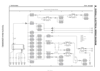
(Cont. next page)1 TOYOTA RAV4
P ow er S ource (E xcept K orea)
DC DDBEBF
1C
1
1 2
10A ECU–B NO. 2
1 2
10A STRG LOCK
1 2
30A ST
1 2
40A BBC
1 2
30A VLVMATIC
1 2
80A EPS
1 2
80A GLOW
1 2
10A HORN
1 2
25A EDU
1 2
10A S–HORN
1 2
10A TURN&HAZ
1 2
30A TOWING–B
1 2
10A ETCS
1 2
7. 5A ALT–S/ICS
1 2
7. 5A AM2
1 2
B–DG
B–DG
B–DG
B–DG(∗3∗11)
B
B
A68(A),A69(B),B85(C),
D1(G),D3(H),D4(J)
1 2
10A DOME
1 2
10A ECU–B NO. 1
21
20A RADIO
1 1
1 2
15A IG2
3
2
5
1
1
1
1
1
1
IG2 Relay
R
1 2
20A EFI–MAIN NO. 2
(∗2, ∗4)
5
1
3
2
1
R
1 2
15A
EFI–MAIN NO. 2 (∗3)
1
EFI–MAIN NO. 2 Relay
1
10A EFI NO. 1
21
21
10A EFI NO. 2
1
1 2
20A EFI–MAIN NO. 1 (∗4)
25A EFI–MAIN NO. 1 (∗3)
30A EFI–MAIN NO. 1 (∗2)
5
1
3
2
1
W
11
EFI–MAIN NO. 1 Relay
1 2
7. 5A EFI NO. 3
1
W
W
W
G
B
V
B
AA
W–BW–B
1 2
50A H–LP–MAIN
1
5
1
3
2
11
1
H–LP Relay
R
R
10A H–LP RH–LO (∗8)
15A H–LP RH–LO (∗7)
21
21
10A H–LP LH–LO (∗8)
15A H–LP LH–LO (∗7)
1
R
3
2
5
1
11
1
DIMMER Relay
R
10A H–LP RH–HI
21
21
10A H–LP LH–HI
1
RR
B
1 C
1
1 2
50A ABS NO. 1
1 2
30A ABS NO. 2
1A
1
W W
1B
1
W W
W W
Y
W
1 G
1 H
(∗4)
(∗4)
(∗3∗12)
(∗3)1 B
(∗2, ∗4)1 A
(∗2)
(∗2)
(∗1)
(∗2)
1 2
30A D/C CUT
(∗2)
(∗4)
(∗3)
(∗2)
(∗4)
(∗3)
(∗6)
∗ 2 : Diesel
∗ 1 : Gasoline
∗ 4 : 2AR–FE
∗ 3 : 3ZR–FE, 3ZR–FAE
∗ 6 : 2AD–FHV, 2AD–FTV
∗ 5 : 1AD–FTV
∗ 8 : Halogen Type
∗ 7 : HID Type
Battery
FL MAIN
3. 0W
∗12 : M/T
∗11 : CVT
120A ALT (∗1)
140A ALT (∗2)
DA
W–B
B–W
(∗5,∗6)
DB
1 J (∗5)
B–DG(∗3)
R
(∗4)
(∗5,∗6)
A
B
C
D
E
MOVERALLELECTRICALWIRINGDIAGRAM
TOYOTARAV4(EM3090E)
http://vnx.su
2. 7 865
(Cont. next page)1 TOYOTA RAV4 (Cont' d)
W
2A
1
1 2
25A STV HTR
1 2
30A TOWING–ALT
1 2
30A H–LP CLN
1 2
30A RDI FAN
1 2
20A DEICER
1 2
7. 5A FOG FR
1 2
50A PTC HTR NO. 3 (∗17)
1 2
50A PTC HTR NO. 2 (∗17)
30A PTC HTR NO. 2 (∗1, ∗18)
1 2
5A DRL
1 2
50A PTC HTR NO. 1 (∗17)
30A PTC HTR NO. 1 (∗1, ∗18)
1 2
50A HTR
1 2
30A CDS FAN
1 2
30A DEF
3
2
5
1
1 2
10A MIR HTR
DEF Relay
W
W
W
19
AG1
15
AG1
Y
W
5
4
7
8
3AM2
AM1
ACC
IG1
IG2
ST2
G4
W
GR
W
W
21
7. 5A IGN
21
5A METER
21
7. 5A A/B
3B
14
LG(∗10)
P
R(∗9)
R(∗10)
R(∗10)
R
P(∗9)
P(∗10)
P(∗10)
P ow er S ource (E xcept K orea)
2 22 2
B B
(∗9)
(∗9) (∗9)
(∗9)
LG
(∗10)
W
(∗10)
(∗10)
(∗10)
IG2D +B
9 A 2 A
G82(A),G84(C)
ACCDIG1D
6 C 4 C
LG
G
G24
51
AGNDSS1SS2
Free
Full
Traveling
SSW1SSW2
C28C30
(∗9)
(∗9)
BR
6
AGND
C24
(∗9)
SS2 SS1 AGND
∗ 1 : Gasoline
∗10 : w/o Entry & Start System
∗ 9 : w/ Entry & Start System
Ignition or Starter
Switch Assembly
Engine Switch
CertificationECU
∗17 : Diesel Except Cold Area Spec.
∗18 : Diesel Cold Area Spec.
A
B
C
D
E
A
B
C
D
E
F
M
TOYOTARAV4(EM3090E)
http://vnx.su
3. 9 10 11 12
1 TOYOTA RAV4 (Cont' d)
W
1 2
20A D/L NO. 2
3A
1
1 2
10A D/L BACK
LG(∗10)
1 2
5A AM1
3C
48
1 2
10A TAIL
1 2
7. 5A PANEL
TAIL Relay
1 2
30A P/SEAT F/L
1 2
30A PBD
1 2
30A P/SEAT F/R
1 2
7. 5A FOG RR
1 2
7. 5A OBD
1 2
10A S/ROOF
1 2
7. 5A STOP
1 2
20A DOOR D
GA
1 2
15A P/OUTLET NO. 2
1 2
5A SFT LOCK–ACC
ACC Relay
3C
45
R(∗9)
R(∗10)
1 2
7. 5A ACC
1 2
15A P/OUTLET NO. 1
1 2
10A ECU–IG NO. 1
1 2
5A EPS–IG
IG1 NO. 1 Relay
3C
43
1 2
7. 5A HTR–IG
1 2
5A ECU–IG NO. 2
1 2
25A WIP FR
IG1 NO. 2 Relay
1 2
15A WIP RR
1 2
7. 5A GAUGE
1 2
10A S–HTR LH
1 2
10A S–HTR RH
IG1 NO. 3 Relay
3D
9
W–B
1 2
15A WSH
7. 5A ECU–IG NO. 3
21
1 2
30A P/W MAIN
1 2
20A DOOR R/R
1 2
20A DOOR R/L
POWER Relay
P(∗9)
P(∗10)
P ow er S ource (E xcept K orea)
∗ 9 : w/ Entry & Start System
∗10 : w/o Entry & Start System
∗13 : LH Wiper Lever Type
∗14 : RH Wiper Lever Type
∗15 : LHD Europe
∗16 : RHD Europe
1
3C
2
3B
1
AG2
L
L
D
3
(∗14)
B
2
(∗13)
B
4
(∗13)
D
1
(∗14)
+B +2
AG22
1
1 2
5A WIPER–S
3C2
3B5
3
2
Windshield Wiper
Switch Assembly
G11(B), G62(D)
A74
R
(∗15)
R
(∗16)
R
(∗15)
R
(∗16)
R
(∗16)
No. 5 Junction
Connector
∗20 : w/o Auto Wiper System
∗19 : w/ Auto Wiper System
A
6
B
2
L
(RHD∗19)
L
(RHD∗19)
(RHD)
(LHD)
L
(RHD ∗20)
G115(A), G116(B)
GD
W–B
No. 27 Junction Connector
A
B
C
D
E
F
MOVERALLELECTRICALWIRINGDIAGRAM
TOYOTARAV4(EM3090E)
http://vnx.su
4. 1 2 3 4
10 TOYOTA RAV4 (Cont. next page)
E ngine C ontrol (3ZR – FE , 3ZR – FA E )
A62(B), B75(D)
25A
EFI–
MAIN
NO. 1
1
2
(BAT)
W
2 3
1 5
1
11
EFI–MAINNO.1Relay
B
EFI–MAINNO.2Relay
11
11
13
25
AA
W–B
Y
W–B
W–B
1
10A
EFI NO. 2
2
1
10A
EFI NO. 1
2
1
V
15A
EFI–
MAIN
NO. 2
R
1
2
(BAT)
15A
IG2
2 5
1 3
1
2
(BAT)
B
1 1
R
HT1B
HT1B
2 3
E2
EX1B
B
W
OX1B
OX1B
4
BA112BA111BA32
W
B
RR
B
W
18 AG3 7 AG3 6 AG3
G32
+B
1
BB
B
B
Y
Y
BATT
W
10A
ETCS
1
2
(BAT)
L
+BM
Y
1
1
R
IG2Relay
5 1
3 2
1 1
1 1
C/OPNRelay
7. 5A
IGNB
3B29
2
(IG)
VN11
Y
4
VN18
W–B
NA
Y
Y
W–B
1
1
1
(∗1)(∗1)
W–B
(∗1)
(∗2)
(∗2)
3 B 2 B46 B 21 B
+B2 +BMREL FC
22 D 135 D 103 D
∗ 1 : 3ZR–FE
P
R
P
R
P
PowerSource
System<1–4>
(∗2)
(∗2)
1 B29 D
W
R
R
W
∗ 2 : 3ZR–FAE
M
5
B
E
V1
L
B
B
W
OxygenSensor(Bank1Sensor2)
ECM
FuelPump
AN21 BA35
BA37
AG319
A
B
C
MOVERALLELECTRICALWIRINGDIAGRAM
TOYOTARAV4(EM3090E)
http://vnx.su
5. 7 865
(Cont. next page)10 TOYOTA RAV4 (Cont' d)
E ngine C ontrol (3ZR – FE , 3ZR – FA E )
EV1+
B
1 2
R
EV1– VCE1
G
3
VVE+ VVE– VC2
B41 B39
VCVVI–VVI+
3
G
VCV1VV1–
R
21
B
VV1+
2
+B
B7
3
A1A+
A1A+
L
Y
A1A–
A1A–
41
HA1A
HA1A
LB
BA31
B28
2
NE–
NE–
B
W
NE+
NE
1
E1
1
E
EKNK
G
R
KNK1
KNK1
2
BRBR
E1
BC
B
BR
(Shielded)
(Shielded)
(Shielded)
(Shielded)
(Shielded)
(Shielded)
BR
BR
Y Y
A62(B), B75(D)
23 D 134 D 133 D 16 D100 D
ALT
GeneratorAssembly
<7–2>
B
(∗1)
78 D 110 D 123 D 124 D 80 D 111 D112 D 82 D 114 D 113 D
IMI IMO
28 B 29 B
IDCodeBox(∗15)
<4–5>
P
LG
BE12 BE11
W
B
B
B
B
∗ 1 : 3ZR–FE
(LHD)
(LHD)CertificationECU(∗14)
<4–5>
TransponderKeyECU(∗12)
<14–2>
TelephoneTransceiver
Assembly(∗13)<15–3>
P
(RHD)
LG
(RHD)
KnockControlSensor(Bank1)
ECM
AirFuelRatioSensor(Bank1Sensor1)
CrankPositionSensor
∗12 : w/ Immobiliser System w/o Entry & Start System
∗13 : w/ Blocking System
∗14 : w/ Entry & Start System w/o ID Code Box
∗15 : w/ Entry & Start System w/ ID Code Box
VVT Sensor (Intake Side)VVT Sensor (Intake Side)VVT Sensor (Exhaust Side)VVT Sensor (Exhaust Side)
A
B
C
A
B
M
TOYOTARAV4(EM3090E)
http://vnx.su
6. 9 10 11 12
(Cont. next page)10 TOYOTA RAV4 (Cont' d)
E ngine C ontrol (3ZR – FE , 3ZR – FA E )
W–BW–B
E04
BC
W–B
E01
W–B
W–B
E02
W–B
ME01
BA
W–B
B
G
L
R
IGT1IGT2IGT3IGT4
W
IGF1
LY
#10
1
2
B19
GY
#20
1
2
B17
BY
#30
1
2
B15
WY
#40
1
2
B13
YY
W–B
EC
AA
W–B
B1
2
E2
ETHA
BR
W
THA
THA
1
G
E2G
E2G
4
R
VG
VG
5
B
3
+B
RB
ACIS
2
1
B44
GB
PRG
2
1
B2
A62(B), B75(D)
59 D 52 D51 D 21 D57 D56 D102 D 55 D54 D 20 D 17 D 18 D 19 D 50 B91 D 92 D 90 D 122 D 50 D 76 D
IgnitionCoils
<8–2><8–3><8–4>
BB
B
ECM
IntakeMassAirFlowMeter
Sub–Assembly
InjectorAssemblyNo.4
InjectorAssemblyNo.3
InjectorAssemblyNo.2
InjectorAssemblyNo.1
VSV(ACIS)
PurgeVSV
(VacuumSwitchingValveAssembly)
BA11
A
B
MOVERALLELECTRICALWIRINGDIAGRAM
TOYOTARAV4(EM3090E)
http://vnx.su
7. 13 161514
(Cont. next page)10 TOYOTA RAV4 (Cont' d)
E ngine C ontrol (3ZR – FE , 3ZR – FA E )
VCP2
L
1 3
R
VPA2 EPA2
P
2
VCP2 VPA2 EPA2
A6
VCPA
B
4 6
W
VPA EPA
Y
5
VCPA VPA EPA
ELS2
P
ELS1
G
V
6 AG1
SPD
V
GR
TACH TC
G
NEO
P
STP
L
A62(B), B75(D)
53 B 51 B 52 B 56 B 54 B 55 B 17 B 30 B 44 B
(RHD)
(LHD)3 AG5
1 AG5
MIRHTRFuse
<41–3>
CertificationECU
<4–2>
P
(∗5)(∗5)
CombinationMeter
Assembly<49–4>
22 B
STA
SB
∗ 5 : w/ Entry & Start System
∗ 3 : CVT
31 B 23 B
DLC3
<13–2>
4 B 9 B
GD
G98
8
6
PWMS
57 B
G60
2
GR
23 AG1
GR
4
21
12
G104
BR
(∗10)(∗10)(∗10)
W–B
(∗10)
W–B
(∗10)
StopLightSwitch
Assembly<17–2>
Park/NeutralPositionSwitch
Assembly(∗3)<4–3><5–3>
ClutchStartSwitch
Assembly(∗4)<4–3><5–3>
∗ 9 : w/o Entry & Start System
W
8 BA3
NSW
W
63 D
CertificationECU
(∗5)<4–2>
(∗3)(∗3)IgnitionorStarterSwitch
Assembly(∗9)<5–2>
PANELFuse
<21–14>
Accelerator Pedal Sensor Assembly
ECM
No.11
JunctionConnector
No.17
JunctionConnectorCombinationSwitchAssembly
∗10 : w/ Sport Switch
SPORT
MSW2
MSW1
∗ 4 : M/T
(∗16)
∗16 : w/ Mirror Heater
M
TOYOTARAV4(EM3090E)
http://vnx.su
8. 17 201918
(Cont. next page)10 TOYOTA RAV4 (Cont' d)
E ngine C ontrol (3ZR – FE , 3ZR – FA E )
B45
2
PIM
PIM
G
BR
EPIM
E2
1R
VCPM
VC
3 2
CAN–
CAN–CAN+
CAN+
4
G
SDWN
SDWN
3
30A
VLVMATIC
1
2
(BAT)
B
+B
1
B
BA33
A62(B), B75(D)
B10
7. 5A
IGN
3B51
2
(IG)
IGSW
B
3B31
GR
B
ST1–
B37
2 4
1 3
StopLight
System<17–1>
118 D 119 D 87 D 49 D 61 D 62 D 12 B 25 B 13 B 26 B
CANP CANN CANH CANL
MultiplexCommunication
System(CANLHD)<2–7>
Multiplex Communication
System (CAN RHD)<3–7>
MultiplexCommunication
System(CANRHD)<3–7>
Multiplex Communication
System (CAN LHD)<2–7>
StopLightSwitchAssembly
A5
(∗2)
(∗2)(∗2)
(∗2)
(∗2)
(∗2)
(∗2)
(∗2)
(∗2)
∗ 2 : 3ZR–FAE
ECM
E.F.I.VacuumSensorAssembly
B46
Continuously Variable Valve Lift Controller Assembly
MOVERALLELECTRICALWIRINGDIAGRAM
TOYOTARAV4(EM3090E)
http://vnx.su
9. 21 242322
(Cont. next page)10 TOYOTA RAV4 (Cont' d)
E ngine C ontrol (3ZR – FE , 3ZR – FA E )
WB
OC1+
2
1
B21
RLG
OE1+
2
1
B23
B
OC1–
LG
OE1– ETHW
BR
THW
GR
VCTA
Y
5 4
L
VTA2 ETA
L
3
VC VTA2 E2
B3
M+
V
2 1
P
M– VTA1
G
6
M+ M–
GE01
(Shielded)
BR
A62(B), B75(D)
7 B 8 B
FANL FANH
R
W
FANNO.3
Relay<48–4>
FANNO.2
Relay<48–4>
75 D 74 D 65 D 64 D 94 D 93 D 58 D 60 D 30 D 84 D 115 D 83 D 116 D
2
1
B4
VTA
IC1 IC2
ECM
E.F.I.EngineCoolant
TemperatureSensor
Throttle Body with Motor Assembly
CamshaftTimingOilControl
ValveAssembly(IntakeSide)
CamshaftTimingOilControl
ValveAssembly(ExhaustSide)
FANNO.1
Relay<48–4>
M
TOYOTARAV4(EM3090E)
http://vnx.su
10. 25 282726
(Cont. next page)10 TOYOTA RAV4 (Cont' d)
C V T and S hift Indicator
A62(B), B75(D)
41 B 42 B 43 B
S SFTU SFTD
AG124 AG111 AG110
LG
Y
L
R
(LHD)
LG
(LHD)
SB
(LHD)
BR
(LHD)
(RHD)B3
(LHD)A1
B1
A3
B5
A5
B4
A4
SFTDSFTUSIG
(IG)
2
27 3C
10A
ECU–IG
NO. 1
GR
L
GD
E
(RHD)B2
(LHD)A2
21
19
6
8
BRW–B
W–B
G104
G98
60 B
AG112
CCS
L
(∗6)
SB
(∗6)
1 A 2 A
CCS ECC
3C24
3B49
6 C 7 C
BA16
BC
BR
(∗8,∗6)
BR
(∗8,∗6)
BR
(∗8,∗6)
BR
(∗8, ∗6)
1 4
2 5
14 A 7 A
3 F 12 C
SUP SDN
18 7
17 6
R
(RHD)
(RHD)
LG
SB
(RHD)
BR
(RHD)
G96
G152
(LHD∗8)
P
(LHD∗8)
W
∗ 6 : w/ Cruise Control
∗ 3 : CVT
∗ 8 : w/ Paddle Shift Switch
120 D 89 D 121 D
VCPT PTO EPTO
3 2 1
VC PTO E2
R
(∗3)
B
(∗3)
W
(∗3)
W–B
6 3
16 5
P
(RHD∗8)
W
(RHD∗8)
W
(RHD ∗8)
P
(RHD ∗8)
G36(A), (B)
Cruise Control
Main Switch
z4(F)
C ruise C ontrol
(3ZR – FE , 3ZR – FA E )
G8(A),z1(C),z4(F)
4 F
Steering Pad
Switch Assembly
z1(C)
+RES
ON–OFF
–SET
CANCEL
ShiftDown
ShiftUp
PaddleShiftSwitchLH
PaddleShiftSwitchRH
GR
P
O
B
R
ECM
No.9
Junction
Connector
No.11
JunctionConnector
No.14
Junction
Connector
No.17
Junction
Connector
SpiralCableSub–Assembly
OilPressureSensor
B32
Transmission Control Switch
MOVERALLELECTRICALWIRINGDIAGRAM
TOYOTARAV4(EM3090E)
http://vnx.su
11. 29 323130
(Cont. next page)10 TOYOTA RAV4 (Cont' d)
NIN–
B
W
NIN+
W
NOTO
129 D 127 D 128 D
NOTB
R
BR
ETHO
6
LG
THO1
1
95 D 96 D 130 D
2
SL
L
L
SLS–
8
Y
SLS+
3
73 D 72 D 68 D
7
DSU
GR
G
DS2
10
W
DS1
5
70 D 69 D 71 D
L
NTO
W
NTB
126 D 125 D
(∗3)
(∗3)
(∗3)
(∗3)
(∗3)
(∗3)
(∗3)
(∗3)
(∗3)
(∗3)
(∗3)
(∗3)
(∗3)
(∗3)
B37
∗ 4 : M/T
99 D 97 D 81 D
P N D
L
(∗3)
Y
(∗3)
B
(∗3)
A62(B), B75(D)
27 B
W
R
AG117
R
R
∗ 3 : CVT
SLS+ SLS– SL DS1 DS2 DSU THO E2
C V T and S hift Indicator
B31
B34
B33
P
R
3
1 2
PL RL NL
8
DL
7
RB
N
D
(∗3)
Back–UpLight
System<16–2>
7. 5A
GAUGE
3B34
2
(IG)
BA18
G
G
(∗3)
(∗3)
L
(∗4)
Park/NeutralPosition
SwitchAssembly
B36
79 D
R
RPark/NeutralPosition
SwitchAssembly
<16–2>(∗3)
ECM
TransmissionRevolutionSensor(Secondary)
TransmissionRevolutionSensor(Turbine)
TransmissionRevolutionSensor(Primary)
CVT Solenoid (Transmission Wire)
LG
BR
W
B
Y
V
O
O
2
1
2
1
2
1
A
B
M
TOYOTARAV4(EM3090E)
http://vnx.su
12. 33 363534
10 TOYOTA RAV4 (Cont' d)
BA12
L
(LHD∗4)
7. 5A
ECU–IG
NO. 3
3B42
2
(IG)
6
4
FA13
FA14
(RHD∗4)
B
(RHD∗4)
L
(LHD∗4)
L
L
(LHD∗4)
B
(RHD∗4)
A72
L
(∗4)
L
(RHD∗4)
B
(RHD ∗4)
∗17 : w/ Gear Shift Indicator
C V T and S hift Indicator
CANLCANH
CAN I/F
5V+B
CAN Controller
G16(A)
I/F
Buzzer
5V+B
5V IC
Display DriverDisplay Driver
LED DriverCPU
SPORT
GearShift
IndicatorUp
(∗17)
GearShift
IndicatorDown
(∗17)
Cruise
SET
CheckEngine
B
CHK
11 A32 A 31 A21 A
ET
R
40 A
(LHD)
Y
Y
(RHD)
22
19
18
22
AG117
10A
ECU–B
NO. 2
1
2
(BAT)
R
R
(RHD)
R
(LHD)
B
39 A
IG+
5A
METER
3D36
2
(IG)
R
GAGE
Multiplex Communication
System (CAN LHD)<2–3>
G99
G101
BR
(RHD)
BR
(LHD)
Multiplex Communication
System (CAN RHD)<3–3>
L
(∗4)
L
(∗4)
1
2
1
2
A1
F1
Combination Meter Assembly
No.12
Junction
Connector
No.14
JunctionConnector
ClutchSwitchAssembly
ClutchSwitchAssembly
No.3
JunctionConnector
∗ 4 : M/T
A
B
MOVERALLELECTRICALWIRINGDIAGRAM
TOYOTARAV4(EM3090E)
http://vnx.su
13. 1 2 3 4
11 TOYOTA RAV4 (Cont. next page)
E ngine C ontrol (2A R – FE )
A62(C), B77(F)
20A
EFI–MAIN NO. 1
1
2
(BAT)
W
2 3
1 5
1
11
EFI–MAINNO.1Relay
B
EFI–MAINNO.2Relay
11
11
23
15
AA
W–B
B
W–B
W–B
1
10A
EFI
NO. 2
1
2
B
20A
EFI–MAIN NO. 2
R
1
2
(BAT)
15A
IG2
2 5
1 3
1
2
(BAT)
Y
IG2Relay
RY
BA35
1
1
P
MREL
46 C
1 1
BATT
1 C
IGSW
B
W
10A
ETCS
1
2
(BAT)
L
+BM
L
Y
7. 5A
IGN
5 1
3 2
1 1
1 1
C/OPNRelay
B
B
3B29
2
(IG)
B
37 C 29 F
Y
B
1
PowerSourceSystem
(ExceptKorea)(∗12)<1–4>
W–B
5 C 6 C
FANL FANH
FANNO.3
Relay<48–4>
FANNO.2
Relay<48–4>
R
W
1
3B31 3B51
AN21
NA
M
4
B
5
E
V1
VN18
W–BW–B(∗14)
B
VN11
Y
Y
P
W–B
B
B
W
B
ECM
FuelPump
BA37
B
1
2
10A
EFI
NO. 1
1
B
∗12 : Except Korea
∗11 : Korea
PowerSourceSystem
(Korea)(∗11)<52–4>
B(∗11)
B(∗11)
B
17
AG3
10
GN1
R(∗13)R(∗13) R(∗13)
W(∗13)
Y(∗13)
Y(∗13)
W(∗13)
FANNO.1
Relay<48–4>
∗14 : w/o Fuel Pump Control ECU Assembly
∗13 : w/ Fuel Pump Control ECU Assembly
A
B
C
D
E
F
G
H
I
J
K
L
MOVERALLELECTRICALWIRINGDIAGRAM
TOYOTARAV4(EM3090E)
http://vnx.su
14. 7 865
(Cont. next page)11 TOYOTA RAV4 (Cont' d)
E ngine C ontrol (2A R – FE )
LY
#10
1
2
B19
GY
#20
1
2
B17
BY
#30
1
2
B15
WY
#40
1
2
B13
20 F 17 F 18 F 19 F
+B
2 C
EC
14 C
+B2
3 C
P
R
W–B
ELS1
4 C
GR
ST1– FC
21 C
W
24 C
A62(C), B77(F)
Y
B B
Y
63 F
NSW
CertificationECU
(∗3)<4–2><53–2>
73 F
ALT
GeneratorAssembly
<7–2><54–2>
BA38
W
(∗1)
W
(∗1)
B
MIRHTRFuse
<41–3>
P
13 C 26 C
CANH CANL
MultiplexCommunication
System(CANLHD)<2–7>
StopLight
System<17–1>
W–B
B
B
W
B
MultiplexCommunication
System(CANRHD)<3–7>
∗ 1 : A/T
1 3
2 4
IgnitionorStarter
SwitchAssembly
(∗7)<5–2>
∗ 3 : w/ Entry & Start System
∗ 7 : w/o Entry & Start System
StopLight
SwitchAssembly
A5
ECM
InjectorAssemblyNo.4
InjectorAssemblyNo.3
InjectorAssemblyNo.2
InjectorAssemblyNo.1
B B
V
PPMP
49 C
AN211
V
VN14
V
7
(∗11)(∗11)(∗11)
VOUT
Y
VCPP
34 C
AN212
Y
VN13
Y
6
(∗11)(∗11)(∗11)
VCC
B
MPMP
19 C
AN27
B
VN16
B
3
(∗11)(∗11)(∗11)
MTRB
BR
EPPM
48 C
AN26
BR
VN15
BR
8
(∗11)(∗11)(∗11)
SGND
W
VPMP
7 C
AN213
W
VN111
W
1
(∗11)(∗11)(∗11)
VGND
AN22
B
VN110
B
5
(∗11)(∗11)
VLVB
Canister Pump Module
V3 4
MGND
W–B
VN112
W–B
AN25
W–B
(∗11)(∗11)(∗11)
BA112
BB
W–B
(∗11)
W–B
(∗11)
B
(∗11)
B(∗11)
∗11 : Korea
R(∗13) R(∗13)
Y(∗13)
W(∗13)W(∗13)
Y(∗13)
∗13 : w/ Fuel Pump Control ECU Assembly
(∗15)
∗15 : w/ Mirror Heater
A
B
C
D
E
F
G
H
I
J
K
L
A
B
C
D
E
M
TOYOTARAV4(EM3090E)
http://vnx.su
15. 9 10 11 12
(Cont. next page)11 TOYOTA RAV4 (Cont' d)
E ngine C ontrol (2A R – FE )
R
HT1B
HT1B
1 4
E2
EX1B
B
W
OX1B
OX1B
3
B25
2
+B
B8
3
A1A+
A1A+
L
Y
A1A–
A1A–
41
HA1A
HA1A
LB
BRBR
E1
BC
W–B
E04
(Shielded)
(Shielded)
W
IGT4
L
IGF1
W
IGT3
G
IGT2
B
IGT1
R
2
+B
BB
B
54 F 51 F 55 F 56 F 57 F 24 F 132 F 100 F 23 F 134 F 133 F 16 F 53 F
A62(C), B77(F)
B B
Ignition
Coils
<9–2><9–3>
BR
ECM
AirFuelRatioSensor
(Bank1Sensor1)
OxygenSensor
(Bank1Sensor2)
B B
BA33 BA31
FPC FP FP– E+B
2 6 5 4
B
(∗13)
R
(∗13)
Y
(∗13)
W
(∗13)
W–B
(∗13)
AN28
1
NA
B
(∗13)
R(∗13)
Y(∗13)
W(∗13)
Fuel Pump Control ECU Assembly
N19
∗13 : w/ Fuel Pump Control ECU Assembly
A
B
C
D
E
A
B
MOVERALLELECTRICALWIRINGDIAGRAM
TOYOTARAV4(EM3090E)
http://vnx.su
16. 13 161514
(Cont. next page)11 TOYOTA RAV4 (Cont' d)
E ngine C ontrol (2A R – FE )
EV1+
B
1 2
R
EV1– VCE1
G
3
VVE+ VVE– VC2
B41 B39
VCVVI–VVI+
3
W
VCV1VV1–
R
21
B
VV1+
X1
1
EKNK
EKNK
G
R
KNK1
KNK1
2
W–B
E01
W–B
BB
ME01
BB
W–B
(Shielded)
(Shielded)
BC
W–B
E02
W–B
BR
BX15 BX11
G
R
(Shielded)
BR
B28
2
NE–
NE–
B
W
NE+
NE
1
(Shielded)
BR
BX12
BR
49 F123 F 124 F 109 F76 F 50 F 58 F 81 F 112 F 111 F 82 F 114 F 113 F
A62(C), B77(F)
(Shielded) (Shielded)
BR
ECM
KnockControlSensor
(Bank1)
CrankPositionSensor
B B
VVT Sensor (Intake Side)VVT Sensor (Intake Side)VVT Sensor (Exhaust Side)VVT Sensor (Exhaust Side)
A
B A
M
TOYOTARAV4(EM3090E)
http://vnx.su
17. 17 201918
(Cont. next page)11 TOYOTA RAV4 (Cont' d)
E ngine C ontrol (2A R – FE )
VCP2
L
1 3
R
VPA2 EPA2
P
2
VCP2 VPA2 EPA2
A6
VCPA
B
4 6
W
VPA EPA
Y
5
VCPA VPA EPA
53 C 51 C 52 C 56 C 54 C 55 C
V
6 AG1
SPD
V
GR
TACH
GD
TC
G
NEO
PP
STP
L
45 C 31 C 23 C11 C 57 C
PWMS
9 C
GR
23 AG1
GR
21
12
G104
A62(C), B77(F)
(∗3)(∗3)
(RHD)
(LHD)3 AG5
1 AG5
Certification
ECU<4–2><53–2>
StopLightSwitchAssembly
<17–2><55–2>
∗ 4 : w/ Sport Switch
6
8
G98
(∗4)(∗4)
BR
(∗4)
W–B
(∗4)
W–B
(∗4)
DLC3
<13–2>
CombinationMeterAssembly
<49–4>
C29C28
P
IMI IMO
LG
IDCodeBox
(∗17)<4–5>
∗10 : w/ Blocking System
CertificationECU
(∗18)<4–5><53–5>
TransponderKeyECU
(∗9)<14–2>
TelephoneTransceiver
Assembly(∗10)<15–3>
Accelerator Pedal Sensor Assembly
ECM
No.11
JunctionConnector
No.17
JunctionConnector
∗17 : w/ Entry & Start System w/ ID Code Box
∗18 : w/ Entry & Start System w/o ID Code Box
∗ 9 : w/ Immobiliser System w/o Entry & Start System
B B
CombinationSwitchAssembly
4
2
G60
SPORT
MSW2
MSW1
A A
MOVERALLELECTRICALWIRINGDIAGRAM
TOYOTARAV4(EM3090E)
http://vnx.su
18. 21 242322
(Cont. next page)11 TOYOTA RAV4 (Cont' d)
E ngine C ontrol (2A R – FE )
WB
OC1+
2
1
B21
RLG
OE1+
2
1
B23
B
OC1–
LG
OE1–ETHW
BR
THW
GR
VCTA
Y
5 4
L
VTA2 ETA
L
3
VC VTA2 E2
B3
M+
V
2 1
P
M– VTA1
G
6
M+ M–
GE01
(Shielded)
BR
74 F 75 F 65 F 64 F59 F 60 F 30 F 127 F 125 F 128 F 126 F
VTA
IC1 IC2
95 F96 F
2
E2
ETHA
BR
94
W
THA
THA
1
E2G
E2G
4
VG
VG
5
B
3
+B
RB
ACIS
F
2
1
B44
GB
PRG
1
2
B2
93 F92 FF91 69 F 68 F
A62(C), B77(F)
R
G
2
1
B4
ECM
E.F.I.EngineCoolant
TemperatureSensor
VSV(ACIS)
PurgeVSV
(VacuumSwitching
ValveAssembly)
Throttle Body with Motor Assembly
CamshaftTimingOil
ControlValveAssembly
(IntakeSide)
CamshaftTimingOil
ControlValveAssembly
(ExhaustSide)
Intake Mass Air Flow
Meter Sub–Assembly
B1
B
BA11
BB
A
M
TOYOTARAV4(EM3090E)
http://vnx.su
19. 25 282726
(Cont. next page)11 TOYOTA RAV4 (Cont' d)
E ngine C ontrol (2A R – FE )
7
D
B
Y
N
8
L
P
3
70 F 71 F 67 F
1
B
IAC1 EIA1
L
2
OUT GND
X2
IA1+
W
5 4
G
IA1–VCIA
B
3
M+ M–
22 F 21 F130 F 131 F 129 F
VDD
BX16 BX17 BX13
R–W
B–R
W–L
BR
LG
BX14 BX18
BR
BR
E C T and A /T Indicator (2A R – FE )C ruise C ontrol (2A R – FE )
A62(C), B77(F)
(∗1)
22 C
STA
Park/NeutralPositionSwitchAssembly
(∗1)<4–3><5–3><53–3>SB
40 C
AG112
CCS
L
(∗5)
SB
(∗5)
1 A 2 A
CCS ECC
3C24
3B493 F 4 F
G8(A),z4(F)
BA16
BC
BR
(∗5)
BR
(∗5)
BR
(∗5)
BR
(∗5)
∗ 5 : w/ Cruise Control
∗ 2 : M/T
∗ 1 : A/T
(∗1)
(∗1)
ClutchStartSwitchAssembly
(∗2)<4–3><5–3>
Cruise Control
Main Switch
z4(F)
+RES
ON–OFF
–SET
CANCEL
B
R
66 F
R
Park/NeutralPositionSwitchAssembly
<16–2>
R
(∗1)
NL
D
N
RB DLRLPL
21
R
P
(∗1)
Back–UpLight
System<16–2>
7. 5A
GAUGE
3B34
2
(IG)
8 BA1
G
G
(∗1)
(∗1)
Park/NeutralPosition
SwitchAssembly
B36
L
(∗2)
SpiralCable
Sub–Assembly
ECM
Intake Air Control Valve Actuator
A
MOVERALLELECTRICALWIRINGDIAGRAM
TOYOTARAV4(EM3090E)
http://vnx.su
20. 29 323130
(Cont. next page)11 TOYOTA RAV4 (Cont' d)
A62(C), B77(F)
BA12
L
(∗2)
L
(LHD∗2)
7. 5A
ECU–IG
NO. 3
3B42
2
(IG)
6
4
FA13
FA14
L
(RHD∗2)
B
(RHD∗2)
L
(LHD∗2)
L
(LHD∗2)
B
(RHD∗2)
B
(RHD∗2)
A72
L
(∗2)
27 C 42 C 43 C
S SFTU SFTD
AG124 AG111 AG110
B18
A1
(RHD)B7
(LHD)A4
B17
A2
(RHD)B6
(LHD)A5
LG
(∗1)
Y
(∗1)
L
(∗1)
R
(∗1∗12)
LG
(∗1∗12)
SB
(∗1∗12)
BR
(∗1∗12)
(RHD)B3
(LHD)A1
B1
A3
B5
A5
B4
A4
SFTDSFTUSIG
10A
ECU–IG
NO. 1
3C27
2
(IG)
GR
(∗1)
L
(∗1)
GD
E
(RHD)B2
(LHD)A2
21
19
6
8
BR
(∗1)
W–B
(∗1)
W–B
(∗1)
G104
G98
G36(A), (B)
E C T and A /T Indicator (2A R – FE )
L
(∗2)
∗ 2 : M/T
1
2
1
2
A1
F1
ECM
G152(B)
G96(A)
No.9JunctionConnectorNo.9JunctionConnector
No.11
Junction
Connector
No.14JunctionConnectorNo.14JunctionConnector
No.17
Junction
Connector
ClutchSwitchAssembly
ClutchSwitchAssembly
No.3
Junction
Connector
Transmission Control Switch
∗ 1 : A/T
∗12 : Except Korea
∗11 : Korea
LG
(∗1∗11)
Y
(∗1∗11)
A
M
TOYOTARAV4(EM3090E)
http://vnx.su
21. 33 363534
(Cont. next page)11 TOYOTA RAV4 (Cont' d)
17
SL1+
W
B
SL1–
16
L
SL2+
9
13 F 4 F 5 F
8
SL2–
LG
GR
SL3+
19
R
SL3–
18
10 F 11 F 12 F
4
NCB
Y
L
NTO
2
Y
NTB
1
116 F 115 F 118 F
21
SL4+
W
B
SL4–
20
L
NCO
3
117 F 8 F 9 F
12
ETHO
BR
BR
SL
6
L
SLU+
14
7 F 3 F 119 F
5
SLU–
LG
GR
SLT+
15
R
SLT–
7
14 F 15 F 6 F
13
THO1
W
120 F
E C T and A /T Indicator (2A R – FE )
A62(C), B77(F)
30 C
AG17
W
RR
R
(∗1)
(∗1)
(∗1)
(∗1)
(∗1)
(∗1)
(∗1)
(∗1)
(∗1)
(∗1)
(∗1)
(∗1)
(∗1)
(∗1)
(∗1)
(∗1)
(∗1)
(∗1)
(∗1)
∗ 1 : A/T
Hall IC
OIL
Y
B78
R
Hall IC
E2SLSLU+SLU–SLT–SL1+SL1–SL2–SL3+SL3–SL4+
B
SL4–NCONCBNTONTB SLT+SL2+
W
G
B
B
L
B
O
B
R
B
GR
B
W
L
Y
Y
ECM
ECT Solenoid (Transmission Wire)
A
MOVERALLELECTRICALWIRINGDIAGRAM
TOYOTARAV4(EM3090E)
http://vnx.su
22. 37 403938
11 TOYOTA RAV4 (Cont' d)
G16(A)
I/F
Buzzer
I/F
5V+B
5V IC
Display DriverDisplay Driver
LED DriverCPU
SPORT
GearShift
IndicatorUp
(∗19)
GearShift
IndicatorDown
(∗19)
Cruise
SET
CheckEngine
IG+B
CHK
CAN Controller
5V+B
CAN I/F
CANH CANL
11 A32 A 31 A21 A
ET
R
R
40 A 39 A
Y
(LHD)
Y
(RHD)
22
19
18
22
AG117
10A
ECU–B
NO. 2
1
2
(BAT)
(A/T)
(A/T)(A/T)
(A/T)
(A/T)
5A
METER
3D36
2
(IG)
B
R
(RHD)
R
(LHD)
R
Multiplex Communication
System (CAN LHD)<2–3>
BR
(RHD)
BR
(LHD)
GE GA
G99
G101
Multiplex Communication
System (CAN RHD)<3–3>
E C T and A /T Indicator (2A R – FE )
Combination Meter Assembly
No.12
Junction
Connector
No.14
Junction
Connector
∗19 : w/ Gear Shift Indicator
A
M
TOYOTARAV4(EM3090E)
http://vnx.su
23. 1 2 3 4
12 TOYOTA RAV4 (Cont. next page)
E ngine C ontrol (D iesel)
(BAT)
2
1
52
31
20A
EFI–MAIN NO. 2
EFI–MAINNO.2Relay
1
1
R
(BAT)
2
1
52
31
25A
EDU
EDURelay
1
1
L
B
1
1
R
B51(A), B52(B), B53(C), B54(D)
IJ2+
BY
2
1
B18
B
IJ2–IJ1+
WB
2
1
B20
W
IJ1–RLF+
BG
2
1
B69
B
RLF–+B
WW
BA33
10A
EFI NO. 1
2
1
1
1
G
B
22
19
A71
GND
W–BW–B
R
W(∗10)
W
1
1
W–B
EFI–MAINNO.1Relay
B
30A
EFI–MAIN NO. 1
1
2
(BAT)
3
5
1
1
1
2
W
7. 5A
EFI NO. 3
2
1
1
1
WW
W–B
AA
B
1
2
10A
EFI NO. 2
1
G
1
1
2 A 4 A 1 D 2 D 1 B 4 B 3 B 6 B
W–B
B
B
W–B
21
BA11
BB
G(∗4)
B
B
B
W–B
(∗4)
InjectorAssemblyNo.2
InjectorAssemblyNo.1
No.2
Junction
Connector
∗ 4 : w/ Air Fuel Ratio Sensor
Injector Driver
PressureDischarge
ValveAssembly
∗10 : A/T
W
W(∗10)
A
B
C
D
E
F
G
H
MOVERALLELECTRICALWIRINGDIAGRAM
TOYOTARAV4(EM3090E)
http://vnx.su
24. 7 865
(Cont. next page)12 TOYOTA RAV4 (Cont' d)
A61(A), B76(E)
E ngine C ontrol (D iesel)
#10
GR
#20
G
LG
#30#40
L
B
PRDINJF
P
V
RLFIJEN
Y
#1
GR
#2
G
#3
LG
#4
L
PRD
B
INJF
P
RLFF
V
IDLO
Y
YL
IJ3+
2
1
B16
L
IJ3– IREL
R
IJ4+
VP
2
1
B14
V
IJ4–
R
W(∗10)
50 E 49 E 48 E 47 E 52 E 51 E 123 E 62 E 44 A
BATT
W
2 A
+B2
B
20 A
+B
B
1 A
MREL
B
45 A1 A 3 A 2 B 5 B 2 C 1 C 8 C 5 C 4 C 6 C 3 C 7 C
B(∗10)
B51(A), B52(B), B53(C), B54(D)
G(∗4)
B
B
B
W–B
B
G(∗4)
B
ECM
InjectorAssemblyNo.4
InjectorAssemblyNo.3
∗ 4 : w/ Air Fuel Ratio Sensor
Injector Driver
W
∗10 : A/T
B
(∗10)
W–B
W(∗10)
A
B
C
D
E
F
G
H
A
B
C
D
E
M
TOYOTARAV4(EM3090E)
http://vnx.su
25. 9 10 11 12
(Cont. next page)12 TOYOTA RAV4 (Cont' d)
E ngine C ontrol (D iesel)
W–B
ME01
W–B
BA
W–B
E01
W–B
W–B
E02
W–B
BC
W–B
E05
W–B
84 E 45 E 44 E 46 E
B1
5
E2
ETHA
BR
WTHA
THA
4
G
EVG
E2G
2
R
VG
FG
1
B
3
+B
YB
ECBV
1
2 B56
YB
VN
1
2
B43
B
GRB
FIV
2
1
B55
65 E 64 E 110 E 87 E 106 E 83 E 105 E
1
5
EGM+
W
E 85 E86
B
EGM– E1
BR
E109
BC
BR
E104E126E125
B8
1
HAF2
HAF2
L
Y
AF2–
AF2–
4
L
AF2+
AF2+
3
G
2
+B
(Shielded)
BA32
G
(Shielded)
(∗4)
(∗2)
(∗4)
(∗2)
(∗4)
83 E
B65
1
2
EOPV
BG
(∗1)(∗1)
A61(A), B76(E)
∗ 2 : Except 1AD–FTV
∗ 1 : 1AD–FTV
∗ 4 : w/ Air Fuel Ratio Sensor
(∗4)
(∗4)
(∗4)
(∗4)
(∗4)(∗4)
B(∗10)
G(∗4)
B
(∗4)
M–
M+
118 E
GR
EGLS
4
VTA
94 E
W
VCEG
2
VC
95 E
BR
EEGL
3
E2
BR
(Shielded)
(∗2)
ECM
IntakeMassAirFlow
MeterSub–Assembly
AirFuelRatioSensor
(Bank1Sensor1)
VRV(EGR)
ExhaustFuelAddition
InjectorAssembly
VSV(EGR)
OilPressureSwitching
ValveAssembly
Bi13 Bi11 Bi12 Bi14Bi15
B
W
V
G
L
i1
ElectricEGRControl
ValveAssembly
W–B
W(∗10)
B(∗10)
W(∗10)
∗10 : A/T
B(∗1) B
(∗1)
A
B
C
D
E
A
B
C
D
E
MOVERALLELECTRICALWIRINGDIAGRAM
TOYOTARAV4(EM3090E)
http://vnx.su
26. 13 161514
(Cont. next page)12 TOYOTA RAV4 (Cont' d)
A61(A), B76(E)
E ngine C ontrol (D iesel)
G–G
R
G+
B29
2
NE–
NE–
B
W
NE+
NE
1
(Shielded)
(Shielded)
(Shielded)
(Shielded)
3
GND
(Shielded)BR
80 E 79 E 103 E 102 E
B
42
31
W–B
GREL
E58
W–B
BA
(BAT)
2
1
80A
GLOW
WWB
B83
1
BATT GL1 GL2 GL3 GL4
R
2
GLW1
L
1
GLW2
L–R
4
GLW3
G
3
GLW4
B67
W1(A), W2(B), W3(C), W4(D)
GND
W–B
W
+B
B
SI DI
GLDO
L
E57 56 E
GLDI
G
(∗2)
(∗2)
(∗2)
(Shielded)
(∗2)
∗ 2 : Except 1AD–FTV
∗ 1 : 1AD–FTV
5 A 4 A 7 A 6 A 40 E 63 E
CANP CANN CANH CANL CAN+ CAN–
Multiplex Communication
System (CAN LHD)<2–7>
(∗10)
(∗10)
B38
3 A 5 A
1 D 1 A 1 B 2 B 1 C 2 C 4 A
(∗1)
(∗1)
(∗1)
(∗1)
(∗1)
(∗1)
(∗1)
(∗2)
(∗1)
(∗1)
∗10 : A/T
Multiplex Communication
System (CAN RHD)<3–7>
BR
(Shielded)
(∗2)
BR
2
1
B26
ECM
CamshaftPosition
Sensor
Glow Plug Controller
1
1E
No.1Glow
PlugConnector
GlowPlugAssembly
CrankPositionSensor
GlowPlug
RelayAssembly
B(∗10)
W(∗10)
B(∗10)
W(∗10)
B
(∗1)
1
BW23 BW24 BW27 BW28
R
(∗1)
L
(∗1)
L–R
(∗1)
G
(∗1)
BW21
B
(∗1)
BW25BW11
B(∗1)
W–B(∗1)
BW26 BW22
L
(∗1)
G
(∗1)
A
B
C
D
E
A
B
M
TOYOTARAV4(EM3090E)
http://vnx.su
27. 17 201918
(Cont. next page)12 TOYOTA RAV4 (Cont' d)
GR
TACH TC
G
A61(A), B76(E)
E ngine C ontrol (D iesel)
B27
1
G2R
G2+
G
W
G2–
G–R
2
B
VCG
VC
3
A6
3
VPA2
P
R
EPA2
2
W
EPA
5
B
VCPA
4
L
VCP2
1Y
VPA
6
78 E 79 E 80 E 55 A 56 A 53 A 57 A 58 A 54 A 13 A 26 A
P
NEO
P
10 A
5
6 4
P
P
A71
P
V
6 AG1
SPD
V
14 A
STA
SB
43 A
(∗1)
(∗1)
(∗1)
(∗13∗2)
(∗1)(∗13∗1)
(∗1)
(RHD)
(LHD)3 AG5
1 AG5
ELS1
G
31 A
∗ 5 : M/T
∗ 2 : Except 1AD–FTV
∗13 : w/ Entry & Start System
DLC3
<13–2>
CombinationMeter
Assembly<49–4>
Certification
ECU<4–2>
EngineStopandStartECU
<6–9>
Park/NeutralPositionSwitchAssembly
(∗10)<4–3><5–3>
VCPA EPA VPA VCP2 EPA2 VPA2
PANELFuse
<21–14>
ClutchStartSwitchAssembly
(∗5)<4–3><5–3>
∗10 : A/T
AcceleratorPedalSensorAssembly
ECM
CamshaftPositionSensor
No.2
JunctionConnector
(∗13)
∗ 1 : 1AD–FTV
W(∗10)
B(∗10) B(∗10)
W(∗10)
A
B
A
B
MOVERALLELECTRICALWIRINGDIAGRAM
TOYOTARAV4(EM3090E)
http://vnx.su
28. 21 242322
(Cont. next page)12 TOYOTA RAV4 (Cont' d)
A61(A), B76(E)
E ngine C ontrol (D iesel)
7. 5A
IGN
3B51
2
(IG)
IGSW
B
3B31GR
B
ST1–
34 A 25 A
INH
P
50 A38 E
NSW
BA38
W
(∗10)
W
(∗10)
W
(∗10)
(∗2)
55 E 54 E
RLO ALT
GeneratorAssembly
<7–2>
R
(∗2)
B
(∗2)
∗10 : A/T
WIPER–SFuse
<32–1><33–4>
15 AA16
P
IMI IMO
LG
IDCodeBox
(∗18)<4–5>
TransponderKeyECU
(∗17)<14–2>
CertificationECU
(∗19)<4–5>
CertificationECUAssembly
(∗13)<4–2>
StopLightSwitch
Assembly<17–2>
STP
L
35 A
IgnitionorStarterSwitchAssembly
(∗14)<5–2>
StopLight
System<17–1>
31
42
A5
StopLightSwitchAssembly
∗13 : w/ Entry & Start System
∗14 : w/o Entry & Start System
∗ 2 : Except 1AD–FTV
P
(RHD)
LG
(RHD)
(LHD)
(LHD)
ECM
W(∗10)
B(∗10) B(∗10)
W(∗10)
∗16 : w/ ID Code Box
∗17 : w/ Immobiliser System w/o Entry & Start System
∗18 : w/ Entry & Start System w/ ID Code Box
∗19 : w/ Entry & Start System w/o ID Code Box
W
(∗10)
W(∗10)
A
B
A
B
C
M
TOYOTARAV4(EM3090E)
http://vnx.su
29. 25 282726
(Cont. next page)12 TOYOTA RAV4 (Cont' d)
E ngine C ontrol (D iesel)
B48
1
2
PCV+
RLG
41 E 81 E
PCV–
R
ETHF
BR
GR
THF
112 E 89 E
ETCI
BR
L
THCI
122 E 99 E
ETCO
BR
P
THCO
121 E 120 E
ETHW
BR
B
THW
111 E 88 E
ETCF
W
L
THCF
76 E 77 E
(∗15)
W–B
(∗15)
W–B
(∗15)(∗15)(∗15)
BR
G104
12
21
GR
AG123
R
G60
A36
PWMS
6
8
G98
GD
22 A 21 A
FANL FANHFANNO.3Relay
<48–4>
FANNO.1Relay
<48–4>
FANNO.2Relay
<48–4>
R
W
(∗4)
(∗4)
(∗4)
(∗4)
(∗1)
(∗1)
∗ 4 : w/ Air Fuel Ratio Sensor
∗15 : w/ Sport Switch
1
2
1
2
1
2
1
2
B59
B49
B4
B60
1
2
B58
∗ 1 : 1AD–FTV
A61(A), B76(E)
ECM
E.F.I.EngineCoolant
TemperatureSensor
SuctionControlValve
No.11Junction
Connector
No.17Junction
Connector
ExhaustGas
TemperatureSensor
CombinationSwitchAssembly
2
SPORT
4
MSW1
MSW2
FuelTemperatureSensor
No.3ExhaustGas
TemperatureSensor
No.2ExhaustGas
TemperatureSensor
W(∗10)
B(∗10) B(∗10)
W(∗10)
∗10 : A/T
W(∗10) W(∗10)
A
B
C
A
B
C
MOVERALLELECTRICALWIRINGDIAGRAM
TOYOTARAV4(EM3090E)
http://vnx.su
30. 29 323130
(Cont. next page)12 TOYOTA RAV4 (Cont' d)
E ngine C ontrol (D iesel)
B70
3
E2S
E2S
L
R
VCS
VCS
1
69 E 91 E
G
VLU
6
119 E
W
VCVL
5
97 E
BR
EVLU
3
96 E
B3
V
VPOP
VC
3
93 E
BR
EPOP
GND
1
70 E
R
POP
VOUT
2
116 E
B66
GR
VCPM (∗1)
VCIB (∗2)
VC5
2
75 E
R
IB
IB
3
116 E
L
EIB
E2
4
77 E
W
THB
THB
1
115 E
B72
2
PR2
PCR2
W
BR
E2M
E2
4
67 E 114 E
6
VC
VCM
V
P
PCR1
PR
5
66 E 68 E
ETHI
BR
Y
THIA
113 E 90 E
BA112 BA111
BR
Y
A61(A), B76(E)
(∗1)
(∗1)
(∗1)
(∗2)
(∗2)
(∗2)
(∗2)
∗ 1 : 1AD–FTV
V
(∗1)
V
(∗1)
∗ 2 : Except 1AD–FTV
1
2
A54
V
M+
2
42 E
P
M–
1
43 E
BR
GE01
82 E
(Shielded)
ECM
FuelPressureSensor
OilPressure
SenderGageAssembly
BatteryCurrent
SensorAssembly
IntakeAir
TemperatureSensor
ThrottleBody
withMotorAssembly
W(∗10)
B(∗10) B(∗10)
W(∗10)
∗10 : A/T
VTA VC E2 M+ M–
IC1
W(∗10) W(∗10)
A
B
C
A
B
C
D
M
TOYOTARAV4(EM3090E)
http://vnx.su
31. 33 363534
(Cont. next page)12 TOYOTA RAV4 (Cont' d)
P
PEX
PEX
2
98 E
BR
EPEX
E2
1
74 E
VC
3
B71
V
VCPM (∗2)
VC
3
93 E
G
PIM
PIM
2
117 E
BR
EPIM
E
1
72 E
B47
V
V(∗4)
L
VNE2
E2
100 E
G
VNVC
VC
101 E
R
VNA
VTA
124 E
MA
M–
W
B
M+
MB
108 E 107 E
BR
BC
(Shielded)
A61(A), B76(E)
(∗4)
(∗4)
(∗4)
(∗4∗2)
(∗3)
(∗1)
(∗1)
(∗1)
(∗1)
(∗1)
V
V(∗1)
∗ 4 : w/ Air Fuel Ratio Sensor
∗ 3 : w/o Air Fuel Ratio Sensor
∗ 2 : Except 1AD–FTV
∗ 1 : 1AD–FTV
23 A
AG112
CCS
L
(∗9)
SB
(∗9)
1 A 2 A 3C24
3B49
BA16
BC
BR
(∗8,∗9)
BR
(∗8,∗9)
BR
(∗8,∗9)
BR
(∗8, ∗9)
14 A 7 A
E ngine C ontrol (D iesel)
C ruise C ontrol
(D iesel)
V
(∗1)
E C T and A /T Indicator (D iesel)
∗ 9 : w/ Cruise Control
∗ 8 : w/ Paddle Shift Switch
P
W
P
W
(LHD ∗8)
(LHD ∗8)
(RHD ∗8)
(RHD ∗8)
F4
CCS ECC
6 C 7 C
SUP
3 F 12 C
SDN
Cruise Control
Main Switch
z4(F)
G8(A),z1(C),z4(F)
Steering Pad
Switch Assembly
z1(C)
+RES
ON–OFF
–SET
CANCEL
ShiftDown
ShiftUp
PaddleShiftSwitchLH
PaddleShiftSwitchRH
GR
P
O
B
R
ECM
SpiralCableSub–Assembly
Bj12 Bj11 Bj13 Bj15 Bj14
V
(∗1)
G
(∗1)
L
(∗1)
W
(∗1)
B
(∗1)
2 B 1 B 3 B 1 A 2 A
j1(A),j2(B)
DieselTurbo
PressureSensor
DifferentialPressure
SensorAssembly
TurbochargerSub–Assembly
W(∗10)
B(∗10) B(∗10)
W(∗10)
∗10 : A/T
(∗1)
(∗1)
W(∗10)
W(∗10)
A
B
C
D
A
B
C
D
E
F
G
MOVERALLELECTRICALWIRINGDIAGRAM
TOYOTARAV4(EM3090E)
http://vnx.su
32. 37 403938
(Cont. next page)12 TOYOTA RAV4 (Cont' d)
10A
EFI NO. 1
2
1
BB
2
1
A1
BA12
L
B
2
1
F1
FA13
B
FA14
LL
L
LL
L
(∗5)
(LHD∗2∗5)
(RHD∗2∗5)
(∗1,∗5)(LHD∗1∗5)
(RHD∗1∗5)(RHD∗5)
(LHD∗5)
(RHD∗5)(RHD∗5)
A61(A), B76(E)
5
1
9 A 61 E 28 A
S SFTU SFTD
AG124 AG111 AG110
4
LG
(∗10)
Y
(∗10)
L
(∗10)
R
(LHD∗10)
LG
(LHD∗10)
SB
(LHD∗10)
BR
(LHD∗10)
(RHD)B3
(LHD)A1
B1
A3
B5
A5
B4
A4
SFTDSFTUSIG
(IG)
2
27 3C
10A
ECU–IG
NO. 1
GR
(∗10)
L
(∗10)
GD
E
(∗10)
(RHD)B2
(LHD)A2
19
21
6
8
BR
W–B
(∗10)
G104
G98
2 5
(RHD∗10)
718
LG
(RHD∗10)
R
17 6
SB
(RHD∗10)
BR
(RHD∗10)
G96
G152
W–B
(∗10)
16
P
(RHD∗8)
W
(RHD∗8)
G36(A), (B)
6 3
LG
(∗10)
(BAT)
22
L
(∗1,∗5)
∗ 5 : M/T
E C T and A /T Indicator (D iesel)
P
W
P
W
(LHD ∗8)
(LHD ∗8)
(RHD ∗8)
(RHD ∗8)
EngineStopand
StartECU<6–3>
A71
20 12
14 13
L
(∗5)
∗ 8 : w/ Paddle Shift Switch
∗ 1 : 1AD–FTV
∗ 2 : Except 1AD–FTV
ECM
No.11
Junction
Connector
No.14Junction
Connector
No.17
Junction
Connector
ClutchSwitchAssembly
ClutchSwitchAssembly
No.2Junction
Connector
No.9Junction
Connector
Transmission Control Switch
W(∗10)
B(∗10)
B(∗10)
W(∗10)
∗10 : A/T
BA23
W(∗10)
W(∗10)
A
B
C
D
E
F
G
A
B
C
D
M
TOYOTARAV4(EM3090E)
http://vnx.su
33. 41 444342
(Cont. next page)12 TOYOTA RAV4 (Cont' d)
R
7 AG1
R
W
12 A 53 E 70 E 73 E
P N D
B
(∗10)
B
(∗10)
Y
(∗10)
L
(∗10)
7. 5A
IGN
3B30
2
(IG)
BA28
IGSWCAN+ CAN– D R
136 7 16 15
E01 E1 SPD STP
Multiplex Communication
System (CAN RHD)<3–7>
(∗10)
(∗10)
B
(∗10)
R
(∗10)
BA BC
9 8 3 12
BA27
AG310
BA29
W–B
(∗10)
BR
(∗10)
V
(∗10)
L
(∗10)
GR
(∗10)
L
(∗10)
Combination
Meter Assembly
<49–4>
StopLight
SwitchAssembly
<17–2>
GR
(∗10)
W–B
(∗10)
BR
(∗10)
Y
(∗10)
+B
18
B79
R
∗10 : A/T
Multiplex Communication
System (CAN LHD)<2–7>
STA
10
LG
(∗10)
STRelay
<5–4>
E C T and A /T Indicator (D iesel)
A61(A), B76(E)
NL
D
N
RB
7
DL
8
RLPL
21
3
R
P
(∗10)
Back–UpLight
System<16–2>
7. 5A
GAUGE
3B34
2
(IG)
8 BA1
G
G
(∗10)
(∗10)
Park/NeutralPosition
SwitchAssembly
B36
L
(∗5)
R
R
71 E
(∗10)
Park/Neutral Position
Switch Assembly<16–2>
Park/NeutralPosition
SwitchAssembly
<16–2>
∗ 5 : M/T
ECM
Transmission Control
ECU Assembly
W(∗10)
B(∗10)
BA37
B
(∗10)
B
(∗10)
Y
(∗10)
(∗10)
W
(∗10)
W
1
BATT
10 BA2
SL1–SL1+SLU–SLU+SLT+ SLT– SL2+ SL2–
B
O
B
R
B
W
B
GR
W(∗10)
(∗10)
W
11
NSW
A
B
C
D A
MOVERALLELECTRICALWIRINGDIAGRAM
TOYOTARAV4(EM3090E)
http://vnx.su
34. 45 484746
12 TOYOTA RAV4 (Cont' d)
2
1
10A
ECU–B
NO. 2
17 AG1
(BAT)
22
18
19
22
(RHD)
Y
Y
(LHD)
A40
R
ET
A21 A31A32 A11
CHK
B
CheckEngine
SET
Cruise
GearShift
IndicatorDown
(∗20)
GearShift
IndicatorUp
(∗20)
SPORT
CPU LED Driver
Display Driver
5V IC
5V+B
I/F
Buzzer
I/F
G16(A)
CAN Controller
5V+B
CAN I/F
CANH CANL
R
R
(RHD)
R
(LHD)
(∗11)
(∗12)
B
39 A
IG+
5A
METER
3D36
2
(IG)
Stop&StartSystem
<6–13>
GAGE
MultiplexCommunication
System(CANLHD)<2–3>
G99
G101
BR
(RHD)
BR
(LHD)
Glow
Display Driver
R
E C T and A /T Indicator (D iesel)
MultiplexCommunication
System(CANRHD)<3–3>
∗11 : w/ Stop & Start System
∗12 : w/o Stop & Start System
Combination Meter Assembly
No.12
Junction
Connector
No.14Junction
Connector
NTONCB NCO NTBSL4+ SL4–SL3+ SL3– THO1SL E2
Y
Y
L
B
G
B
L
TPS1 TPS2 TPS3
B
O
GR
B79
Transmission Control
ECU Assembly
∗20 : w/ Gear Shift Indicator
A
M
TOYOTARAV4(EM3090E)
http://vnx.su
35. 1 2 3 4
13 TOYOTA RAV4
TCTAC
GD
SG CGBAT
(BAT)
42 3D
7. 5A
OBD
G14
DLC3
CANHCANL
MultiplexCommunication
System(CANRHD)<3–5>
BR
G
L
GR
G
16
GR
9 13 614 5 4
BC
BR
W–B
D LC 3
TS SILLVL
78
G
Y
R
HeadlightLeveling
ECUAssembly<19–2>
PowerSteeringECU
Assembly<26–1>
12
ECM
<10–15>
<11–19>
<12–19>
MultiplexCommunication
System(CANLHD)<2–5>
2
AG116
3C16
3B15
3C23
3B49
BA16
BRBR
9
11
1
5
6
7
G95
G108
G98
W–B
(LHD)
W–B
(RHD)
BR
(RHD)
BR
(LHD)
5
∗ 1 : w/ Immobiliser System w/o Entry & Start System
∗ 2 : w/ Blocking System
∗ 3 : w/ Headlight Beam Level Control (Automatic)
5
6
7
TransponderKey
ECUAssembly
<14–3>
HeadlightLeveling
ECUAssembly
<19–2>
141513
12
G
(LHD)
Y
(RHD∗1)
Y
(LHD∗1)
GR
(∗2)
B
(LHD∗3)
B
(RHD∗3)
(RHD)
TelephoneTransceiver
Assembly<15–3>
No.8JunctionConnector
No.11
JunctionConnector
No.20JunctionConnector
B
(∗4)
OccupantDetection
ECU<58–9>
No. 9
Junction Connector
G96
No. 25
Junction Connector
G113
OP4
1
VFrontSeatInnerBelt
AssemblyRH<58–9>
(∗3)
(∗4)
∗ 4 : Korea
MOVERALLELECTRICALWIRINGDIAGRAM
TOYOTARAV4(EM3090E)
http://vnx.su
36. 1 2 3 4
14 TOYOTA RAV4
10A
ECU–B
NO. 2
2
(BAT)
G99
+B
7. 5A
IGN
3C37
(IG)
IG
G6
W
R
ANT1 ANT2
GND
GD
KSW IND
R
BEW–B
19
22
R
1 5
4 151 2
5 3 8
2
Immobiliser S ystem (w /o E ntry & S tart S ystem)
AG117
1
(RHD)
R
19
20
BE
G101
(LHD)(LHD)
(RHD)
BR
11
10
LG
G113
(RHD)
LG
3
2
G96
BR
(LHD)(LHD)
ANT1 ANT2
Transponder Key ECU Assembly
G88
13
EFIO EFII
12
AG121 AG120 AG320 AG311
TelephoneTransceiver
Assembly<15–3>
ECM
<10–7>
<11–20>
<12–24>
ECM
<10–7>
<11–20>
<12–24>
P
LG
P
LG
LG
(∗1)
P
(∗1)
P
(LHD)
LG
(LHD)
P
(RHD)
LG
(RHD)
6
2
BR
Un–LockWarningSwitch
Assembly<21–65>
P
(LHD)
P
(RHD)
9
D
Y
(LHD)
Y
(RHD)
DLC3
<13–4>
GR
(LHD)
GR
(RHD)
TelltaleLightAssembly
<21–58>
G98
W
CTY
FrontDoorCourtesyLight
SwitchAssemblyLH<21–30>(∗2)
7
(RHD)
(RHD)
(RHD)
(LHD)
(LHD)
∗ 2 : Middle East
∗ 1 : w/ Blocking System
No.9
Junction
Connector
No.11JunctionConnectorNo.12
Junction
Connector
No.14
Junction
Connector
No.25
Junction
Connector
Transponder Key Coil
M
TOYOTARAV4(EM3090E)
http://vnx.su
37. 1 2 3 4
15 TOYOTA RAV4
B locking S ystem
G96
W–B
SB
BLK1BLK4
LG
BR
SIL
Telephone Transceiver Assembly
G58(A), G147(B), G148(C)
R
BLK2BLK3
10A
ECU–B
NO. 1
1
2
(BAT)
7. 5A
IGN
3C37
(IG)
11
8
BR
+B IG2
P
GE
E
LG
P
LG
GR
P
2
DLC3
<13–4>
ECM
<10–7><11–20>
Certification
ECUAssembly(∗1)<4–5>
Navigation
Antenna
Telephone
Antenna
5
9
3B16
3D41
G100
W
AG121 AG120
TransponderKeyECUAssembly
(∗2)<14–2>
No.9
Junction
Connector
No.13JunctionConnector
∗ 2 : w/o Entry & Start System
∗ 1 : w/ Entry & Start System
1 C
Instrument Panel
Integration Antenna Assembly
G147(B), G148(C)
1 B
6 A 9 A 3 A 8 A 7 A 2 A 1 A12 A
MOVERALLELECTRICALWIRINGDIAGRAM
TOYOTARAV4(EM3090E)
http://vnx.su
38. 1 2 3 4
16 TOYOTA RAV4
B ack– U p Light
7. 5A
GAUGE
3B34
(IG)
BA18
B35
BA14
3B40
3E4
3C34
UN22
2
1
U15
2
1
U16
UA
12
14
11
10
139
G109
G110
V
(RHD)
V
(LHD)
Radio & Display
Receiver Assembly
(∗7)<47–3>
Clearance
Warning
ECUAssembly
<45–3>
GG
(A/T,CVT)
G
(M/T)
R
(A/T,CVT)
R
(M/T∗1)
R
(M/T∗2)
R
(A/T,CVT,M/T∗1)
RR
RW
W
W
W–B
W–B
W–B
R
(RHD)
R
(LHD)
R(A/T ∗3)
R(A/T, CVT)
∗ 2 : 2AR–FE
∗ 1 : Except 2AR–FE
∗ 3 : Diesel
3E27
BOption
Connector
(Towing)
<60–1>
2
R
1
RB RL
Park/NeutralPosition
SwitchAssembly
B36
1
2
ECM
<10–31>
<11–27>
<12–44>
Transmission
ControlECU
Assembly
<12–43>
E E
B B
Back–Up
Back–Up
RearCombinationLightLH
RearCombinationLightRH
No.21
Junction
Connector
No.22
Junction
Connector
Back–UpLightSwitchAssembly
∗ 5 : Radio Receiver Type
∗ 6 : Navigation Receiver Type
∗ 7 : Radio & Display Receiver Type
BE
(LHD)
BE
(RHD)
Navigation Receiver
Assembly
(∗6)<47–3>
Radio Receiver
Assembly
(∗5)<47–3>
2
M
TOYOTARAV4(EM3090E)
http://vnx.su
39. 1 2 3 4
17 TOYOTA RAV4
S top Light (E xcept K orea)
7. 5A
STOP
3B35
2
(BAT)
7. 5A
ECU–IG
NO. 3
3B41
2
(IG)
3 1
4
5 2
22
222
STOPLP
Relay
18
16
3B18
3C35 3E11 3E26 3B17
GM27
Stop
Tail
1
B
4
E
M19
MB
Stop
Tail
1
B
4
E
N13
NB
9
8
3
1
UN28
2
1
UA
L
(∗1)
LG
(∗1)
V
(∗1)
W
(∗2)
L
(∗1)
W
(∗1)
W
(∗1)
W
(∗1)
L
(∗1)
3B43
3B443B23
L
(∗1)
L
L
(∗3A/T)
L
LW
L
L
(∗8)
L
(∗7)
L
(∗7)
L
(∗1)
W–BW–B
W–B
W–BW–B
N22
U1
N24
A73
6 17
7 5
BrakeActuator
Assembly
<23–4>
TransmissionControl
ECUAssembly<12–43>
BrakeActuator
Assembly
<23–4>
3B39
L
(∗2)
L
(∗2)
3B22
LECM
<10–19>
<11–18>
<12–26>
3C39
L
(∗4)
ShiftLockControl
ECU<43–3>
∗ 2 : w/o Hill–Start Assist Control
∗ 1 : w/ Hill–Start Assist Control
∗ 4 : CVT, A/T
∗ 3 : Diesel
∗ 8 : w/o Option Connector (Towing)
∗ 5 : w/ Entry & Start System
∗ 7 : w/ Option Connector (Towing)
E
B
L
(∗4∗5)
CertificationECU<4–19>
3C21
1
2
StopLightSwitchAssembly
A5
2
R
(∗7)
OptionConnector
(Towing)<60–2>
CenterStopLightAssembly
No.31
Junction
Connector
No.33
Junction
Connector
No. 4 Junction Connector
RearCombinationLight
AssemblyRH
RearCombinationLightAssemblyLH
BrakeActuator
Assembly
<23–4><24–1>
UN2
1
WW–B
MOVERALLELECTRICALWIRINGDIAGRAM
TOYOTARAV4(EM3090E)
http://vnx.su
40. 1 2 3 4
18 TOYOTA RAV4 (Cont. next page)
LG
SB
3C32
3B38
AD
A41(A),A42(B)
LLW–BW–B
3C31
3B24
A16(A),A17(B)
YYW–B
3C33
OuterRearView
MirrorAssemblyRH
I8
GC
LLW–B
W–B
W–B
3C13
OuterRearView
MirrorAssemblyLH
J8
GB
YYW–B
W–B
W–B
IG21 7 JG2
11
10
Turn S ignal and H azard W arning Light
13 B 7 B
LL LR
9 B10 B
A11
B20 (∗2)
A12 (∗1)
B19
CR
LH
TL EL TR
Off
TurnSwitch
HeadlightDimmerSwitchAssembly
G13(A),G63(B)
(∗1)15 A
(∗2)16 B
Turn
Turn
EE
BB
Turn
WP
B
E
HeadlightAssemblyLH
HeadlightAssemblyRH
(LHD)
BR
(RHD)
BR
G16(A),G17(B)
CPU
5V IC
5V+B
39 A 40 A
IG+ B
ET
21 A
GAGE
(LHD)
Y
Y
(RHD)
22
19
18
22
AG117
10A
ECU–B
NO. 2
1
2
(BAT)
5A
METER
3D36
2
(IG)
B
R
(RHD)
R
(LHD)
R
G99
G101
EL ER
10A
TURN&HAZ
1
2
(BAT)
AG11
1 B
LL
B
I/F
I/F
I/F
TurnLH
TurnRH
W–B
(RHD)
BE
18 B
13 A
A29
HAZ
TL TR
GD
6
11
13
7
GR
B3
HAZ
W–BW–B
E
TB
IG212 JG212
CombinationMeterAssembly
No.12
Junction
Connector
No.14
Junction
Connector
Hazard
∗ 2 : RH Turn Lever Type
∗ 1 : LH Turn Lever Type
5
RH
CR
CR
EL
CR
8
1
W–B
(RHD)
No.20
Junction
Connector
G108
10
No. 11
Junction Connector
G98
W–B
(LHD)
TelltaleLight
Assembly
G43
I/F
Buzzer
W–B
AB
∗ 5 : Except Korea
∗ 4 : Korea
(∗5)B2
(∗4)A1
(∗4)B1
(∗5)A2
(∗5)B1
(∗4)A2
(∗4)B2
(∗5)A1
AA
W–B
(∗7)
(∗6)
Stop&StartSystem
<6–13>
∗ 7 : w/o Stop & Start System
∗ 6 : w/ Stop & Start System
10
11
Turn
WP
B
E
A
B
MOVERALLELECTRICALWIRINGDIAGRAM
TOYOTARAV4(EM3090E)
http://vnx.su
41. 7 865
18 TOYOTA RAV4 (Cont' d)
3C14
SBSB
M19
3E14
Y
N13
NB
W–B
W–BW–B
GM217
3 3
4 4
EE
TRN TRN
MB
Turn S ignal and H azard W arning Light
Turn
Turn
9
8
N22
OptionConnector
(Towing)<60–2>
3E28 3E29
G
Y
No.31
Junction
Connector
RearCombinationLightAssemblyRH
RearCombinationLightAssemblyLH
(∗3)
(∗3)
∗ 3 : w/ Option Connector (Towing)
A
B
M
TOYOTARAV4(EM3090E)
http://vnx.su
42. 1 2 3 4
19 TOYOTA RAV4
10A
ECU–IG
NO. 1
3B50
(IG)
L
IG HDLP
BR
E1
GB
W–B
SBR SHRL SGR
R
Y
BR
RH+ RH– RHT
A56
G
W–B
Y
LH+ LH– LHT
A57
W
W–B
BR
A67
Headlight Leveling ECU Assembly
INIT PRST
Y
BB
WNGSPDR
LG
3
1 3 12 19 21
155
1
182411 1723109
23 1 2
616
2
DLC3
<13–3><13–4>
H–LPRelay
<21–1>
A21
CPU
G16(A), G17(B)
Combination Meter Assembly
GE
ET
5V IC
LG
B4
LVWG
LG
H eadlight B eam Level C ontrol (A utomatic)
O1(A), O2(B)
SHGSHRRSHB
BR
Y
R
Headlight Assembly LH Headlight Assembly RH
RHM+ RH E RH T
Headlight
Leveling Motor
LHM+ LH E LH T
Headlight
Leveling Motor
AN12 AN11 AN18
ON11 ON12 ON13
(4WD)1 A
(2WD)1 B
2 A
2 B
3 A
3 B
R
Y
BR
3B8
3C5
W–B
AG714 AG715
Y
(LHD)
B
(RHD)
CombinationMeter
Assembly<49–3><49–4>
VY
AG716
(RHD)
Y
(LHD)
AG717
BR
(RHD)
GA
(LHD)
BR
Headlight
BeamLevel
R
(LHD)
R
(LHD)
Y
(RHD)
Y
(∗1)
(∗2)
B
(RHD)
R
39 A 40 A
IG+ B
5A
METER
3D36
2
(IG)
Stop&StartSystem
<6–13>
10A
ECU–B
NO. 2
1
2
(BAT)
G101
AG119
18
22
22
19
G99
∗ 1 : w/ Stop & Start System
∗ 2 : w/o Stop & Start System
Rear Height Control Sensor Sub–Assembly
No.12
Junction
Connector
No.14
Junction
Connector
5V+B
MOVERALLELECTRICALWIRINGDIAGRAM
TOYOTARAV4(EM3090E)
http://vnx.su
43. 1 2 3 4
(Cont. next page)2 TOYOTA RAV4
G1G2E1E2C1C2
C
13 14
N32
1
3 2
U18
10
CANL CANH
Y
W
CANL CANH
R
W
CANL CANH
B
W
C9
CANL CANH
G92(A)
BR
W
No. 2 CAN Junction Connector
G128(A), G129(B), G130(C), G131(D),
G132(E), G133(F), G153(G), G154(H)
NB
W–BBR
CANP CANN
W
B
W
G
W
L
2 F 1 F
2 B1 B
N31
V
W
W
B
M ultiplex C ommunication S ystem (C A N LH D )
E
CANH CANL
(∗9)9 H
(∗8)
10 H
∗ 6 : w/ Entry & Start System
W
L
CANHCANL
2 D 1 D
G86
5 6
(4WD)
(4WD)
∗ 7 : w/ Stop & Start System
9 20 8 19 10 21
UN12 UN113
G
(∗13)
W
(∗13)
(∗13)
(∗13)
(∗13)
(∗13)(∗13)
9
7
N22
GN22 GN23
(∗13∗15)
(∗13∗15)
1
2
7
8
N30
B
(∗13∗14)
W
(∗13∗14)
V
(∗13∗14)
W
(∗13∗14)
B
(∗13)
W
(∗13)
(∗10)9 N10 N
(∗6)
(∗6)
(∗12)8 A
(∗11)11 B
9 A
12 B
A1A2
W
G
G16(A)
CANHCANL
H2H1
LG
W
G87(C)
CANLCANH
(∗7)
(∗7)
(∗13)
(∗13)
CertificationECU
G84(C)
A/CAmplifierAssembly
G80(A),G81(B)
32 A31 A
∗ 9 : Navigation Receiver Type
∗ 8 : Radio Receiver Type
∗10 : Radio & Display Receiver Type
∗12 : Manual Air Conditioner
∗11 : Automatic Air Conditioner
∗13 : w/ Power Back Door
∗15 : w/o Power Seat
∗14 : w/ Power Seat
(∗13)
15 C 14 C
Radio & Display
Receiver Assembly
G143(N)
Navigation
Receiver Assembly
G139(H)
Radio Receiver Assembly
G48(C)
22 A 13 A 15 C 16 C
CombinationMeterAssembly
EngineStopandStartECU
No.31JunctionConnector
No.4CANJunctionConnector
No. 5 CAN Junction Connector
4WDECUAssembly
AirbagSensorAssembly
No.1CANJunctionTerminal
Multiplex Network Door ECU
∗20 : Korea
9 3
W
(∗13∗14∗20)
R
(∗13∗14∗20)
Ne117 Ne116
W
(∗13∗14∗20)
L
(∗13∗14∗20)
e6(A)
PowerSeatSwitchAssembly
8 AA7
A
B
C
D
MOVERALLELECTRICALWIRINGDIAGRAM
TOYOTARAV4(EM3090E)
http://vnx.su
44. 7 865
CANL CANH
B
W
DLC3
G14
CANL CANH
R
W
L
W
CANL CANH
PowerSteeringECUAssembly
h1(A)
G118(A),G119(B),G120(C),G121(D),
G122(E),G123(F),G124(G),G125(H)
No.1CANJunctionConnector
W
LG
CANL CANH
MainBodyECU
G78(A),G79(B)
Y
CANL CANH
SteeringSensor
G12
P
W
W
V
W
2 B 1 B 2 G 1 G 2 C 1 C A2 1 A
2 D D1 2 F 1 F 2 E 1 E
614
4 A8 A 13 A 14 A
CANN CANP
9 B10 B
B
W
2 3
B
W
B
W
2 TOYOTA RAV4 (Cont' d)
M ultiplex C ommunication S ystem (C A N LH D )
(∗13)
(∗13)
(∗13)
(∗13)
hG12 hG11
W
R
(∗5)25 A14 A
14 B (∗4)25 B
A63(A),A64(B)
A2A1
B2B1
N27(A),N28(B),N29(C)
Y
W
AN23 AN24
GN311 GN312
W
LL
W
CANLCANH
(∗2)6 A
(∗1)26 B
7 A
13 B
Y
W
CANP CANN
(∗17)4 A
(∗3, ∗19)25 B
5 A
12 B
CA3P CA3N
A58
B
W
CAN+ CAN–
6 5
CAN+ CAN–
Y
B
B79
(∗2A/T)
(∗2A/T)
2 7
C2C1
W
RR
W
CA1P CA1N
R1
(∗18)
(∗18)
(∗18)
(∗18)
RN16 RN15
1 HH2
G
W
Q13
CA1PCA1N
B
W
(∗16)
(∗16)
(∗16)
(∗16)
GQ15GQ16
12 6
(∗3)62 D
(∗2)63 E
61 D
40 E
B46
(∗3)
(∗3)
L
Y
CAN–CAN+
24
ECM
A61(A), A62(B), B75(D), B76(E)
∗ 1 : Gasoline
∗ 2 : Diesel
∗ 4 : w/ VSC
∗ 3 : 3ZR–FAE
∗ 5 : w/o VSC
∗13 : w/ Power Back Door
∗16 : w/ Lane Departure Alert
∗17 : 1AD–FTV
(∗3,∗17,∗19)
(∗3,∗17,∗19)
∗18 : w/ Blind Spot Monitor
CA2P CA2N
1 6
RN13 RN14
MN112 MN111
TM16 TM17
T1
1
CA2N CA2P
6
W
B
W
B
B
W
B
W
No.3CANJunctionConnector
LaneDepartureWarningCamera
BlindSpotMonitorSensorLH
BlindSpotMonitorSensorRH
Transmission Control
ECU Assembly
Continuously Variable
Valve Lift Controller
Assembly
Generator Control
ECU Assembly
BrakeActuator
Assembly
(∗18)
(∗18)
(∗18)
(∗18)
(∗18)
(∗18)
(∗18)(∗18)
∗19 : 2AR–FE Korea 2WD
3 2
AG14 AG15
A
B
C
D
M
TOYOTARAV4(EM3090E)
http://vnx.su
45. 1 2 3 4
20 TOYOTA RAV4
H eadlight B eam Level C ontrol (M anual) H eadlight C leaner
11
GB
W–BW–B
W–B
W–B
W–B
R
L
R
L
RR
L
LG
4
9
1
A71
AC
A484
W–BW–B
E
7. 5A
ECU–IG1
NO. 3
3B42
5
4
2
30A
H–LP CLN
M
1
2
2
3 6 1
(IG) (BAT)
IG PB HDLO
A47
A72
L
Y
L
B
BRH–LPRelay
<21–1>
BR
(LHD)
(LHD)
(LHD)
B
E
L
(RHD)
BR
(RHD)
LG
(RHD)
G68A56
2
T
A57
W–B
10A
H–LP
LH LO
1
2
8
R
10
AG39
R
R
4
6
5
G94
23
AG79
10
11
9
G113
AG78
1
AG38
14
13 12
15
A72
3C5
3B8
W–B
1
3 2
2
FRWA
W
5
WindshieldWasherMotor
andPumpAssembly
<32–7><33–3>
RH E
RHM+ RH T
LH E
LHM+ LH T
Headlight Leveling MotorHeadlight Leveling Motor
Headlight Cleaner Control Relay
Headlight Assembly RH
HeadlightAssemblyLH
Headlight Leveling Switch
No. 7
Junction
Connector
No. 25
Junction
Connector
No. 2 Junction Connector
No. 3
Junction Connector
No.3JunctionConnector
HeadlightCleanerMotorandPumpAssembly
R
(BAT)
2
1
50A
H–LP–
MAIN
2 3
1 5
11
1
1
H–LPRelay
R
R
M
TOYOTARAV4(EM3090E)
http://vnx.su
46. 1 2 3 4
21 TOYOTA RAV4 (Cont. next page)
(BAT)
50A
H–LP–MAIN
1
3 2
H–LPRelay
1
15A
H–LP LH–LO (∗11)
10A
H–LP LH–LO (∗12)
1
2
1
2
AB
3B37
1
2
AD
A18
HRLY
W–B
Main Body ECU
G78(A), G79(B)
(∗12)
1 1
5 1
R
R
1 1
R
∗12 : Halogen Type
∗11 : HID Type
R
(∗12)
R
(∗11)
W–B
(∗12)
3
2
W–B
(∗11)
W–B
(∗12)
R
15A
H–LP RH–LO (∗11)
10A
H–LP RH–LO (∗12)
1
2
R
(∗11)
1
W–B
(∗11)
A40
H eadlight (E xcept K orea)
7. 5A
ACC
2
(ACC)
3B54
LG
1529
W–B
W–B
BR
A39
LOLO
EE
Low(HID)
Light
ControlECU
E
LO
A19
3
2
Low(HID)
Light
ControlECU
E
LO
Low
Low
HeadlightAssemblyLH
HeadlightAssemblyLH
HeadlightAssemblyRH
HeadlightAssemblyRH
1
ACC DIM
22
W–B
2 3
1 5
11
11
DIMMERRelay
R
R
R
1
10A
H–LP
RH–HI
2
1
10A
H–LP
LH–HI
2
1
1 1
1
2
A37
HI
EHigh
1
2
A21
HI
E
High
AG118
W–B
W–B
R
R
R
R
2
BR
BR
HeadlightAssemblyLH
HeadlightAssemblyRH
∗48 : w/ Headlight Cleaner System
No.14
Junction
Connector
No.12
Junction
Connector
(∗9)
(∗8)
Stop&
Start
System
<6–13>
2
Y
(LHD)
22
19
18
22
B
R
(BAT)
2
1
10A
ECU–B
NO. 2
(IG)
36 3D
A2131 A
A40
32 A
39 A
Buzzer
I/F
CAN
Controller
5V
IC
(LHD)
BR
(RHD)
GA
5V+B
AUTO
High
Beam
CAN I/F
Multiplex
Communication
System (CAN LHD)<2–3>
GE
ET
BR
CANHCANL
BIG+
CPU
LED Driver
17 AG1
(LHD)
R
(RHD)
R
(RHD)
Y
G99
G101
5A
METER
I/F
Illumination
Combination Meter Assembly
G16(A), G17(B)
Multiplex
Communication
System (CAN RHD)<3–3>
R
∗ 9 : w/o Stop & Start System
∗ 8 : w/ Stop & Start System
Headlight
Leveling
ECU<19–1>
Headlight
Cleaner
Control
Relay<20–4>
1
2 3
No. 3
Junction
Connector
A72
BR
(∗11)
BR
(∗48)
5V+B
A
MOVERALLELECTRICALWIRINGDIAGRAM
TOYOTARAV4(EM3090E)
http://vnx.su
47. 7 865
(Cont. next page)21 TOYOTA RAV4 (Cont' d)
HF AHU
R
G
Y
HEAD
L
8 A 28 A5 A 29 A
14 B
17 A
11 B
20 A
17 B
14 A
12 B
19 A
15 A
16 B
Main Body ECU
G78(A), G79(B)
GR
2 B
9 A
8 A
3 B
27 A 1 A
L
(∗41)
RFOGFFOG
A utomatic Light C ontrol (E xcept K orea),
Light A uto Turn O ff S ystem (E xcept K orea) and
Light R eminder (E xcept K orea)
CLTE CLTS CLTB
CLTE CLTS CLTB
V
G
W
22 A 21 A 20 A
3 5 6
MultiplexCommunication
System(CANLHD)<2–6>
CANHCANLCANP
A14A13
CANN
B9B10
HeadlightDimmerSwitchAssembly
G13(A),G63(B)
B13
A18
W
BEL T H A BFGLFG
Front
Off(HL)
AUTO
Tail
Head
HFHUEL
High
Low
Flash
Off
Rear
(∗42)7 A
(∗42)
(∗43)
(∗43)
Dimmer Switch
Fog Light SwitchLight Control Switch
H eadlight (E xcept K orea)
9
8
1
4
6
7
GD
G108
G98
BR
(LHD)
BR
(RHD)
W–B
W–B
W–B
5
101
7
BR
(LHD)
BR
(RHD)
W–B
(LHD)
W–B
(RHD)
W
MultiplexCommunication
System(CANRHD)<3–6>
(RHD)
(LHD)
∗41 : w/ Rear Fog Light
(∗40)
∗40 : w/ Front Fog Light
∗42 : LH Turn Lever Type
∗43 : RH Turn Lever Type
No.11
Junction
Connector
No.20
Junction
Connector
RearFog
FrontFog
GR
(∗41)
B11
S
Y
(∗40)
B12
FOG
AG41
Y
(∗40)
HighBeam
A14
–
A19
+
G16(A),G17(B)
CombinationMeterAssembly
R
R
8
G2
AutomaticLight
ControlSensor
(LHD)
BR
(RHD)
BR
G95
No.8
Junction
Connector
Y(∗40)
GR(∗41)
EL T LFG
BBFGAHHFHU
(∗49)
(∗49)
(∗49)
(∗49)
∗49 : w/ Automatic Light Control System
A
A
B
C
M
TOYOTARAV4(EM3090E)
http://vnx.su
48. 9 10 11 12
(Cont. next page)21 TOYOTA RAV4 (Cont' d)
R ear Fog LightFront Fog Light (E xcept K orea)
FFGO
3B56
13
1 5
2 3
2 2
2 2
FOGFRRelay
7. 5A
FOG FR
2
2
(BAT)
A20
A15
A46
AD AB
Y
Y
Y
W–B
W–B
W–B
W–B
W–B
Y
Y
GW
L
(∗3∗40)
(∗4∗40)
(∗3∗40)
(∗4∗40)
RFGO
3D52
27
3 1
5 2
44
4 4
FOGRRRelay
7. 5A
FOG RR
3C25
2
(BAT)
NB
9
1
RN18
SR14
GN34
RN11
SR11
2
1
2
1
N22
S5
S6
W
(∗41)
SB
(∗41)
GR
(∗41)
GR
(∗41)
LLL
(∗41)
L
(∗41)
L
(∗41)
W–B
(∗41)
W–B
(∗41)
W–B
(∗41)
W–BW–BW–B
G
(∗41)
W
G(∗41)
G(∗40)
W
Main Body ECU
G78(A), G79(B)
∗40 : w/ Front Fog Light
∗ 3 : 2AR–FE
∗ 4 : Except 2AR–FE
(∗41)(∗41)
(∗41)(∗41)(∗41)
(∗40)
(∗40)(∗40)
(∗40)
(∗40)(∗40)(∗40)
(∗40)
∗41 : w/ Rear Fog Light
FogLight
AssemblyLH
FogLight
AssemblyLH
FogLight
AssemblyRH
RearFogLight
AssemblyLH
RearFogLight
AssemblyRH
No.31JunctionConnector
(∗40)
Y(∗40)
GR(∗41)
1
2
1
2
1
2
A
B
C
A
B
C
MOVERALLELECTRICALWIRINGDIAGRAM
TOYOTARAV4(EM3090E)
http://vnx.su
49. 13 161514
(Cont. next page)21 TOYOTA RAV4 (Cont' d)
NB
N13
M19
RearLightAssemblyRH
U9
E
B
RearLightAssemblyLH
U8
E
B
W–B
2
1
2
1
LicensePlateLight
AssemblyLH
U4
LicensePlateLight
AssemblyRH
U5
G
G
W
W
W
W
W–B
W–B
W–B
W–B
1 1
22
TAIL
W
A30
W–B
Taillight (E xcept K orea)
Tail
Tail
E
E
B
B
4
4
W–B
W–B
W–B
2
2
Tail
Tail
Stop
Stop
TRLY
14
TAILRelay
10A
TAIL
2
1
3A1
120A
ALT (∗1)
140A
ALT (∗2)
1B1
2
(BAT)
7. 5A
PANEL
2
1
3B28 3E38 3C363C38
G
(∗41)
AD
(∗14)1 B
1 A (∗13)2 A
(∗13)3 A
(∗14)2 B
A36(A),(B)
AB
(∗14)1 B
1 A (∗13)2 A
(∗13)3 A
(∗14)2 B
A22(A),(B)
UAMB
9
8
N22
GM28
AG33
UN2108 7 10
9
G
G
G
G
G
G
B
(RHD)
B
(LHD)
W–B
W–BW–B
W–B
W
WG
G
18 17
16 N24
G
G(∗41)
G(∗40)
W
B(LHD)
B(RHD)
5A
DRL
2
2
(BAT)
3 1
5 2
2 2
22
DRL
Relay
DRL DRLE
725
3B52
R(∗13)
R(∗13)
B
(∗13)
R
(∗13)
R
(∗13)
Main Body ECU
G78(A), G79(B)
3E23
BROptionConnector
(Towing)<60–1>
∗40 : w/ Front Fog Light
∗13 : w/ Daytime Running Light
∗14 : w/o Daytime Running Light
∗ 2 : Diesel
∗ 1 : Gasoline
(∗40)
Clearance
(∗13)
DaytimeRunning
Light(∗13)
Clearance(∗14)
B B
E
11
G
A70
Clearance
(∗13)
DaytimeRunning
Light(∗13)
Clearance(∗14)
B B
E
3B11
GECM
<10–15>
<12–20>
∗41 : w/ Rear Fog Light
Headlight
AssemblyLH
HeadlightAssemblyRH
No.31
Junction
Connector
No. 33
Junction
Connector
No. 1 Junction Connector
RearCombination
LightAssemblyRH
RearCombination
LightAssemblyLH
∗ 4 : Except 2AR–FE
∗50 : w/ Option Connector (Towing)
(∗50)
(∗4)
A
B
C
A
B
M
TOYOTARAV4(EM3090E)
http://vnx.su
50. 17 201918
(Cont. next page)21 TOYOTA RAV4 (Cont' d)
G78(A), G79(B)
Main Body ECU
Illumination (E xcept K orea)
8 A
G26
8
6
2 A
G27
5
4
9 A
ILL+
ILL–
G1
2
3
20 18 17
GR
(∗37)
SB
(∗37)
BR
(∗38)
L
(∗37)
LG
(∗37)
LG
(∗38)
1 A
G51
4
5
R
(∗10)
P
11 A
G70
5
1
V
(∗8)
LG
(LHD∗8)
4 A
G60
5
1
LG
(∗23)
R
(∗23)
15
LG
(RHD∗8)
GD
21
G72
7
8
5 B
G
(RHD∗18)
13
LG
(LHD∗18)
G73
2
3
10 A
W
(LHD∗18)
14
LG
(LHD∗18)
22
W
(LHD)
G
(LHD)
202118
22 12
GD
W–B
(RHD)
W
(RHD)
W–B
(LHD)
162219
G107(A), (B)
G95
G106
G112
LG
GR
(∗38)
LG
(∗5)
6 A 1 B
L
(RHD)
L
(LHD)
B(LHD)
B(RHD)
B(LHD)
B(RHD)
L(RHD)
L(LHD)
G(LHD ∗18)
G(RHD ∗18)
G(LHD)
R(∗23)
W(RHD)
W(LHD)
P(∗10)
LG
GR(∗38)
LG(∗5)
∗ 5 : A/T, CVT
(∗10)
∗10 : w/ VSC ∗38 : w/ Power Heater (Combustion Type)
∗37 : w/ Seat Heater∗ 8 : w/ Stop & Start System
∗18 : w/ Power Back Door
SeatHeater
SwitchRH
SeatHeaterSwitchLH
CombinationSwitchAssembly
PowerBackDoor
MainSwitch
BackDoor
Control
Switch
No. 8 Junction Connector
No.18
Junction
Connector
No. 19 Junction Connector
No.24
Junction
Connector
Traction
ControlSwitch
CombinationSwitchAssembly
∗44 : w/ ECO MODE Switch
ILL+
ILL– ILL– ILL– ILL–
ILL+ILL+ILL+
LG(RHD ∗18)
LG(RHD ∗18)
ILL–ILL–
ILL+ILL+
ECOMODE
(∗44)
SPORT
MSW–
MSW+
HeaterSwitchAssembly
B11 B10 8 B B2 9 B (RHD)
(LHD) A7
∗23 : w/ Sport Switch
A
B
A
B
C
D
E
F
G
H
I
J
K
L
M
N
MOVERALLELECTRICALWIRINGDIAGRAM
TOYOTARAV4(EM3090E)
http://vnx.su
51. 21 242322
(Cont. next page)21 TOYOTA RAV4 (Cont' d)
Illumination (E xcept K orea)
9
G
(LHD∗18)
10 3
1
4
LG
22 21
11 20 19 17 6
G
(RHD∗18)
2
L
(RHD)
GR
(LHD)
L
(LHD)
BR
(LHD∗12)
B
(LHD)
Y
(LHD)
BE
(LHD4WD)
9 103
B
(RHD)
G50
7
8
BE
(RHD4WD)
2
SB
(4WD)
ILL+
3
BR
(RHD∗12)
W–B
(∗12)
AG38
14
15
3B8
3C5
GB
A72
W–BW–BW–B
4
Y
(RHD)
GND1
ILL+
7
(∗22)10 L
(∗21)10 F
(∗20)10 A
(∗20)7 A
(∗21)7 F
(∗22)7 L
GEG
(RHD)
BR
G
(LHD)
(∗12)
G111
G68
E
4
1
GR
(RHD)
711895
G104
B(LHD)
B(RHD)
L(RHD)
L(LHD)
G(LHD ∗18)
G(RHD ∗18)
G(LHD)
R(∗23)
W(RHD)
W(LHD)
P(∗10)
LG
GR(∗38)
LG(∗5)
W
(RHD)
W
(LHD)
P
LG
(∗17)
BR
(∗16)
LG
(∗24)
V
LG
(∗52)
SB
(4WD)
GR(LHD)
LG(∗5)
GR(∗38)
LG(∗17)
BR(∗16)
LG(∗24)
V
LG(∗52)
Main Body ECU
G78(A), G79(B)
∗17 : Manual Air Conditioner
∗16 : Automatic Air Conditioner
∗24 : w/ Blind Spot Monitor
∗10 : w/ VSC
∗38 : w/ Power Heater (Combustion Type)
∗12 : Halogen Type
(∗12)(∗12)
(∗10)
∗ 5 : A/T, CVT
∗20 : Radio Receiver Type
∗18 : w/ Power Back Door
∗22 : Radio & Display Receiver Type
∗21 : Navigation Receiver Type
∗23 : w/ Sport Switch
Radio&Display
ReceiverAssembly
G141(L)
NavigationReceiver
Assembly
G137(F)
RadioReceiver
Assembly
G46(A)
BR
(LHD∗12)
13 A 11 A
5 C 3 C
SteeringPadSwitchLH
SteeringPadSwitchRH
R
B
IL+2 –DP
G8(A),z1(C)
SteeringPadSwitchAssembly
z1(C)
GD
6
9
G98
W–BW–B
SpiralCable
Sub–Assembly
Headlight Leveling Switch
No.11JunctionConnector
No. 17 Junction Connector
No. 23 Junction Connector
Differential
LockSwitch
No.3
JunctionConnector
ILL+
ILL–
No.7
Junction
Connector
G94
G
(LHD)
1610
∗52 : w/ Downhill Assist Control
A
B
C
D
E
F
G
H
I
J
K
L
M
N
A
B
C
D
E
F
G
H
I
M
TOYOTARAV4(EM3090E)
http://vnx.su
52. 25 282726
(Cont. next page)21 TOYOTA RAV4 (Cont' d)
Illumination (E xcept K orea)
8
GR
(RHD)
G29
2
3
LG
(∗52)
2
SB
(∗52)
ILL–
DIM
G43
19
18
V
10
W
G75
9
10
LG
(∗24)
1
R
(∗24)
G25
6
1
GR
(∗38)
3
G
(∗38)
ILL–
ILL+
G64
2
1
LG
(∗5)
4
G
(∗5)
E
ILL+
W–BV
(∗17)
ILL–
ILL+
G20
1
4
BR
(∗16)
11
V
(∗16)
ILL–
ILL+
G23
6
5
LG
(∗17)
5
G
(∗17)
REC
ILL+
G22
4
7
BR
(∗17)
6
G
(∗17)
9
BR
GD
W–BW–B
G103
GR(LHD)
LG(∗52)
V
LG(∗24)
BR(∗16)
LG(∗17)
GR(∗38)
LG(∗5)
Main Body ECU
G78(A), G79(B)
(∗26)7 B
(∗25)9 A
(∗25)5 A
(∗26)5 B
G21(A),(B)
∗25 : Australia, Middle East
∗ 5 : A/T, CVT
∗38 : w/ Power Heater (Combustion Type)(∗17)
(∗17)
∗17 : Manual Air Conditioner
∗16 : Automatic Air Conditioner
∗24 : w/ Blind Spot Monitor
∗26 : Except ∗25
No.2HeaterControl
Sub–Assembly
No.1HeaterControl
Sub–Assembly
No.3HeaterControl
Sub–Assembly
TelltaleLightAssembly
No. 16 Junction Connector
FrontWiperDeicerSwitch
DownhillAssistControlSwitch
ShiftIllumination
(IndicatorLight
WireSub–Assembly)
ILL– ILL– ILL–
ILL+ ILL+ ILL+
AirConditioning
ControlAssembly
∗51 : w/ Parking Assist (TOYOTA Parking Assist–Sensor)
21
18
G104
No.17
Junction
Connector
6
8
G98
No.11
Junction
Connector
ClearanceWarningECU
Assembly<45–2>(∗51)
∗52 : w/ Downhill Assist Control
(∗17)
BlindSpotMonitorMainSwitch
(WarningCancelingSwitchAssembly)
A
B
C
D
E
F
G
H
I
MOVERALLELECTRICALWIRINGDIAGRAM
TOYOTARAV4(EM3090E)
http://vnx.su
53. 29 323130
(Cont. next page)21 TOYOTA RAV4 (Cont' d)
Main Body ECU
G78(A), G79(B)
RearDoorCourtesyLightSwitchAssemblyLH
N8
M6
RearDoorCourtesyLightSwitchAssemblyRH
RCTY
A24
1
A6
GM219
1
LCTY
GN219
2
1
FLCYFRCY
A19
1
FrontDoorCourtesyLightSwitchAssemblyLH
N6
FrontDoorCourtesyLight
SwitchAssemblyRH
M4
3C42 3E40
Y
W
Y
W
L
W
W
L
GM218
Interior Light (E xcept K orea)
(LHD)(LHD)
SB
(RHD)
SB
(RHD)
TransponderKeyECU
Assembly<14–3>(∗39)
BCTL BCTY
204
3E25 3E33
N1
P
LG
LG
9 11
8
N24
UN29
LGW
(∗18)
W
(∗19)
BackDoorLock
Assembly<28–7>
10A
DOME
1
2
(BAT)
3B12
3C46 3C47
(∗7)
GR
KILE
26
44 3D
4
2
ILL–
ILL+
G6
5 2
3 1
DOMR
15 A
3D50
3
BCYL
Y
GQ27
DOMECUT
Relay
R
P
P
P
(∗7)
WY
W
∗18 : w/ Power Back Door
∗19 : w/o Power Back Door
∗ 7 : w/o Entry & Start System
∗39 : Middle East
10
LG
(∗18)
MultiplexNetwork
DoorECU<28–8>
No.2RoomLightAssembly
No.33
Junction
Connector
1
2
B
L
TransponderKeyCoil
W(∗19)
44
4 4
P
(RHD)
(RHD)
(RHD)
(RHD)
(RHD)
Y
R
DOMECUT
Relay
Y
5
5 5
(LHD)
(LHD)
(LHD)
P
(LHD)
5
5 2
3 1
P
(LHD)
Ignition Key
Cylinder Light
A
B
M
TOYOTARAV4(EM3090E)
http://vnx.su
54. 33 363534
(Cont. next page)21 TOYOTA RAV4 (Cont' d)
Main Body ECU
G78(A), G79(B)
GR
ILE
1
35 3D
GQ25
2 3
+B1CTY
GND
1
Q12
Q11
1
GND
CTY +B1
32
Q9
2
E
CTY B
13
Q3
Q2
GQ26
GB
WW
(∗27)
W
(∗27)
W
(∗28)
W
(∗28)
W
W
W
W
W
W
W
W
W
W
(∗28)
W
(∗27)
WW–B
Interior Light (E xcept K orea)
W
W
W W
W
∗27 : w/ Sliding Roof
∗28 : w/o Sliding Roof
VanityLightAssemblyRH
VanityLight
AssemblyLH
No.1RoomLightAssembly
MapLightAssembly
MapLightAssembly
W(∗19)W(∗19)
∗19 : w/o Power Back Door
W
W
1
2
VanityLight
SwitchLH
(Visor
AssemblyLH)
Q4
1
2
VanityLightSwitchRH
(VisorAssemblyRH)
Q1
2
1
2
1
A
B A
MOVERALLELECTRICALWIRINGDIAGRAM
TOYOTARAV4(EM3090E)
http://vnx.su
55. 37 403938
21 TOYOTA RAV4 (Cont' d) (Cont. next page)
20A
D/L NO. 2
(BAT)
D/ULRelay
D/LRelay
GND1
GA
ACT– ACT+
M
LSSR UL L
E
NA
LN16
W–B
3E32
LSR
M
LSSR UL L
E
3C41
KM1
YY
YY
LA–V
LA–B
LA–B
LA–R
10 LN1 5 KM1
3E17
R
GM12 GM54 GM53
Y
B
R
3D12
R
3E1 3D4
B
BR
3B55
BZR
ABAD
8 11 9 21
3D9
W–B
W–BW–B
(LHD∗6)
W–B
(RHD∗6)
13 KM11013 LN1LN15
L
5
2
D oor Lock C ontrol (E xcept K orea)
A12
1
2
Unlock
Detection
Unlock
Detection
Main Body ECU
G78(A), G79(B)
6 B
5 A
1 B
1 A
(∗30)4 B
(∗29)2 A
6 A
(∗30)9 B
(∗29)4 A9 A 3 A
L4(A), (B)
LN14 LN114 LN17
R
(∗29)
B
(∗29)
L
(∗29)
P
(∗29)
B
(∗29)
L
(∗29)
A10
W–B
(∗29)
4
6
W–B
N23
W–B
(∗30)
6 B
9 A
1 B
3 A
(∗30)4 B
(∗29)4 A
10 A
(∗30)9 B
K4(A), (B)
MA
KM16
W–B
(∗29)2 AA5 1 A
R
(∗29)
B
(∗29)
L
(∗29)
A6
W–B
(∗29)
6
4
W–B
M26
W–B
(∗30)
L(∗29)
B(∗29)
R(∗29)
L(∗29)
B(∗29)
P(∗29)
W–B
(∗29)
W–B
(∗29)
(∗29)
W–B
∗30 : w/o Double Locking
∗29 : w/ Double Locking
WirelessDoorLockBuzzer
No.29
Junction
Connector
No.32
Junction
Connector
Rear Door Lock with
Motor Assembly RH
Rear Door Lock with
Motor Assembly LH
(∗29)
W–B
W(∗19)W(∗19)
∗19 : w/o Power Back Door
E DLSR UNDL DL E DLSR UNDL DL
M M
∗ 6 : w/ Entry & Start System
(∗6)(∗6)
A
A
B
C
D
E
F
G
H
I
M
TOYOTARAV4(EM3090E)
http://vnx.su
56. 41 444342
21 TOYOTA RAV4 (Cont' d)
Main Body ECU
G78(A), G79(B)
M
I10(A),(B)
LSSRL UL
E
GC
W–B
3 JG1
B
P
B
B
2 JG1
3D5
B
UL L
L
3D
11 JG1
R
IG1
11
R
3D3
LSFL UL2 L2
M
J10(A),(B)
LSSRL UL
E
GB
W–BB
B
B
UL L
(LHD∗30)
3D13
P
LSFR
B
R
JG210 JG211
A7 A12 A11 A18
IG210 IG211 IG114
7 JG2
W–B
W–B
BR
P
(LHD∗30)
BR
(LHD∗30)
(LHD∗30)
LG
B
R
L
(RHD)
R
(RHD)
(RHD)
L
(RHD)
R
13
(RHD)
(RHD)
Unlock
Detection
KeyUnlock
KeyLock
Unlock
Detection
KeyUnlock
KeyLock
ACTS ACTR
43
9 B11 B
7 A 11 A
IG31 IG315
5
DLPD
IG323
L
(∗29)
B
(∗29)
B
(∗29)
L
(∗29)
B
(∗29)
9 B 4 B (∗29)3 B
B
(∗29)
L
(∗29)
B
(∗29)
M
(∗29)10 B
(∗30)8 A
8 B
UNDLDLDLSR
E
IG212
W–B
(∗29)
W–B
2 B
4 A
1 B
1 A
7 B
7 A
(RHD)
(LHD)
7 IG1
8 IG1
W–B
4 A
4 B
1 A
3 B
8 A
(∗29)8 B
(∗30)9 A
7 B
(∗30)7 A
10 A
E DLSR
5 B
W–B
(∗29)
6 B
M
DL UNDL
2 B (∗29)1 B
P
(∗29)
L
(∗29)
B
(∗29)
G66
P(∗29)
B(∗29)
L(∗29)
R(∗29)
B(∗29)
L(∗29)
P(∗29)
L(∗29)
B(∗29)
G115(A), G116(B)
D oor Lock C ontrol (E xcept K orea)
(Cont. next page)
∗29 : w/ Double Locking
∗30 : w/o Double Locking
P(∗29)
B(∗29)
L(∗29)
R(∗29)
B(∗29)
L(∗29)
FrontDoorLock
withMotorAssemblyRH
FrontDoorLock
withMotorAssemblyLH
No. 27
Junction
Connector
B5
A5
B6
(∗30)A6
Double Lock Door Control Relay Assembly
W(∗19)W(∗19)
∗19 : w/o Power Back Door
D ouble Locking
A
B
C
D
E
F
G
H
I
A
B
C
D
E
F
G
H
I
J
MOVERALLELECTRICALWIRINGDIAGRAM
TOYOTARAV4(EM3090E)
http://vnx.su
57. 45 484746
21 TOYOTA RAV4 (Cont' d)
Main Body ECU
G78(A), G79(B)
10A
D/L
BACK
3D6
(BAT)
G
(∗29)
10A
ECU–B
NO. 1
1
2
(BAT)
3B16
3D41
CPUB
7
22
18
G111
BR
RW
8 A 12 A 8 B 12 B 9 A 7 B
GM114 GM126 GN38 GN39JG326 JG314
KM17 KM114
L
(∗29)
B
(∗29)
B
(∗29)
L
(∗29)
L
(∗29)
B
(∗29)
L
(∗29)
B
(∗29)
L
(∗29)
B
(∗29)
B
(∗29)
L
(∗29)
L
(∗29)
B
(∗29)
G115(A), G116(B)
10
GN215
P
(∗29)
P
(∗29)
KM14
GM18
P
(∗29)
R
(∗29)
P
(∗29)
11
P
(∗29)
9
8
P
(∗29)
DLPP
6
G99
1
+B
9
MPX1
V
(∗29)
G
(∗29)
G66
P(∗29)
B(∗29)
L(∗29)
R(∗29)
B(∗29)
L(∗29)
B(∗29)
L(∗29)
P(∗29)
D ouble Locking
(Cont. next page)
JG39
P
(∗29)
(∗29)
GND
14
GD
W–B
(∗29)
KOFF
2 A
RPOWERRelay
<30–1><31–1>
15
3E15
BECU
30
R
R
R(∗54)
∗55 : w/ Theft Warning Siren Assembly
No. 12
Junction Connector
No.23
JunctionConnector
No. 27 Junction Connector
R(∗55)
Double Lock Door Control Relay Assembly
W(∗19)W(∗19)
∗54 : w/ Tilt Sensor
(∗54)
(∗55)
V(∗29)
∗29 : w/ Double Locking
∗19 : w/o Power Back Door
A
B
C
D
E
F
G
H
I
J
A
B
C
D
M
TOYOTARAV4(EM3090E)
http://vnx.su
58. 10A
D/L BACK
(BAT)
R
D/LBACKRelay
U12
W
M
TR+
8 3E 3D9
GA
W–B
W–B
UN211
3 2
1
ACT–
D+ ACT+
6
2
Courtesy
L1 UL1
9 A 10 A
3D21
3D20
3D33
3D32
JG114 JG116
2 B
2 A
(∗32)9 B
(∗31)9 A
(∗31)1 A
(∗32)1 B
ULL
E
J5(A),(B)
GB
JG27
W–BW–BP
(LHD)
B
(LHD)
P
(LHD)
B
(LHD)
P
(LHD)
B
(LHD)
W–B
(LHD)
ULL
E
I5
2 8
9
IG13 IG112
V
(RHD)
W
(RHD)
V
(RHD)
W
(RHD)
GC
IG212
W–BW–BW–B
(RHD)
IG
3D40
32
5A
ECU–IG
NO. 2
3C15
2
(IG)
18
12
12
15
L
(LHD∗9)
L
(RHD∗9)
G
(LHD∗9)
G
(RHD∗9)
G100
G151
BDSU
23 A
GN218
UN27UN15
CertificationECU
<4–16>
R
(∗7)
L
(∗6)
Y
(∗6)
YW
W
(∗6)
2
UA
W–BW–B
31
U7
W
(∗19)
21 TOYOTA RAV4 (Cont' d)
D ouble Locking
W ireless D oor Lock C ontrol
(w /o E ntry & S tart S ystem)
49 525150
∗19 : w/o Power Back Door
∗31 : w/ Jam Production
∗32 : w/o Jam Production
∗ 6 : w/ Entry & Start System
∗ 9 : w/o Stop & Start System
EngineStop
andStartECU
<6–11>
BE
(LHD∗8)
L
(RHD∗8)
∗ 8 : w/ Stop & Start System
∗ 7 : w/o Entry & Start System
PowerWindowRegulatorMasterSwitchAssembly
PowerWindowRegulatorMasterSwitchAssembly
BackDoorOpenerSwitchAssembly
BackDoorLockAssembly
No.9
Junction
Connector
No.13
Junction
Connector
(LHD)
(RHD)(RHD)
(LHD)
B ack D oor O pener
(E xcept K orea)
R(∗54)R(∗54)
(Cont. next page)
Main Body ECU
G78(A), G79(B)
R(∗55) R(∗55)
W(∗19)
V(∗29)V(∗29)
∗29 : w/ Double Locking
∗55 : w/ Theft Warning Siren Assembly
∗54 : w/ Tilt Sensor
Door Lock
Control Switch
Door Lock
Control Switch
E
ULL
(∗19)
(∗19)
(∗19)(∗19)
Open
Lock
A
B
C
D
A
B
C
MOVERALLELECTRICALWIRINGDIAGRAM
TOYOTARAV4(EM3090E)
http://vnx.su
59. Main Body ECU
G78(A), G79(B)
(Cont. next page)21 TOYOTA RAV4 (Cont' d)
53 565554
(∗45)
No.23
Junction
Connector
No.22
Junction
Connector
No.13
Junction
Connector
20
21
G110
G113
2
1
3 GM2
G
223
16 A 4 A
RDA PRG
2 GM2
Y
5 11
4 8
GM412
SB
(LHD)
P
(LHD∗45)
SB
(RHD)
P
(RHD∗45)
R
(LHD∗44)
R
(RHD∗44)
W
6
W
R
(∗45)
R
(∗47)
Y
10
Door Control Receiver
M10(A)
PRG CSEL
2 A3 A
(∗47)
R
∗44 : w/ Tire Pressure Warning System
∗45 : w/o Tire Pressure Warning System
∗46 : FMVSS138 Type
∗47 : ECE–R64 Type
(∗46)
DATA
5 A
Y
GND
1 A
W–B
GM411
1
9
14
22
R
(LHD)
R
(RHD)
W
(RHD)
W
(LHD)
3B16
3D41
G100
G111
10A
ECU–B
NO. 1
1
R
2
(BAT)
MB
W–B
No.25
Junction
Connector
No. 30
Junction
Connector
M27
R(∗54) R(∗54)
W ireless D oor Lock C ontrol (w /o E ntry & S tart S ystem)
R(∗55) R(∗55)
V(∗29)V(∗29)
∗29 : w/ Double Locking
∗54 : w/ Tilt Sensor
∗55 : w/ Theft Warning Siren Assembly
Tire Pressure Warning ECU and Receiver
(Door Control and Tire Pressure Monitoring
System Receiver Assembly)<22–1>
Tire Pressure Warning ECU and Receiver<22–3>
(∗46)
W
No.30
Junction
Connector
M27
Y
(∗47)
W
(∗47)
G
(∗47)
G
(∗47)
W
(∗47)
Y
(∗45)
14
12
Y
(∗45)
Y
(∗45)
(∗44)
No.30
JunctionConnector
M27
10A
ECU–B
NO. 1
1
R
2
(BAT)
A
B
C
A
B
C
M
TOYOTARAV4(EM3090E)
http://vnx.su
60. Main Body ECU
G78(A), G79(B)
10A
S–HORN
1
2
(BAT)
AC
HCTY
B
1
S–HORN
Relay
Security Horn Assembly
A13
V
L
4 4
4 4
2 3
1 5
53 3D
17
V
SH
22 B
IND
HORNRelay
<35–3>
HORN
28
34 3D
12
B
PKB
1
G37
ParkingBrakeSwitchAssembly
3D55
Radio&DisplayReceiver
Assembly(∗22)<47–3>B
E
+
NavigationReceiver
Assembly(∗21)<47–3>
4 3 15 13
2 12
CertificationECU(∗6)<4–18>
GR
GR
Y
(LHD)
Y
(RHD)
G
(RHD)
G
(LHD)
G94
G152
LP
21
5 B
AG311AG31
4
6
(∗9)1 B
(∗8)1 A
(∗8)2 A
(∗9)2 B
R
(LHD)
R
(RHD)
R
(RHD)
R
(LHD)
R
W–B
(LHD)
W–B
(RHD)
W–B
(LHD ∗53)
AG75
L
(LHD∗53)(LHD∗53)
(LHD∗53)
(LHD∗53)
(LHD∗53)
AG312
B
(LHD∗53)
A70
A50(A),A59(B)
(Cont. next page)
Theft D eterrent
57 605958
2
R(∗54) R(∗54)
∗ 9 : w/o Stop & Start System
∗ 8 : w/ Stop & Start System
∗19 : w/ Power Back Door
PBDS
27 B
1
4
9
3
1
11
6
7
GD
W–BR
(∗19)
BR
(LHD∗19)
W–B
(LHD∗19)
W–B
(RHD∗19)
W–B
(RHD ∗19)
BR
(RHD ∗19)
22 17
G95G73
5
G108
BackDoorControlSwitch
No.7
JunctionConnector
No.8
Junction
Connector
No.14
Junction
Connector
No. 20
Junction
Connector
21 TOYOTA RAV4 (Cont' d)
Telltale
Light
Assembly
G43
No.11
JunctionConnector
G98
E
13
(RHD)
(LHD)
11
W–B
∗ 7 : w/o Entry & Start System
∗ 6 : w/ Entry & Start System
R(∗55) R(∗55)
HoodCourtesySwitch
(HoodLockAssembly)
No.1
Junction
Connector
V(∗29)V(∗29)
∗29 : w/ Double Locking
∗55 : w/ Theft Warning Siren Assembly
∗54 : w/ Tilt Sensor
EngineStopand
StartECU<6–5>
5
R
(∗8)
Security
Indicator
W–B
(LHD)
B
(LHD ∗53)
∗53 : w/ Security Horn
∗21 : Navigation Receiver Type
∗22 : Radio & Display Receiver Type
TransponderKeyECU
Assembly(∗7)<14–4>
A
B
C
A
B
C
MOVERALLELECTRICALWIRINGDIAGRAM
TOYOTARAV4(EM3090E)
http://vnx.su
61. 54 3D
16
R
LIN2
SlidingRoofControlECU
<27–4>
FrontPowerWindowRegulator
MotorAssemblyLH<30–3>
2
1
G94
L
3
P
(LHD)
(LHD)
GCS
6 B
GN26
CSIF
5
GND
1
4
8
N23
PPW–B
GCS
19
3D38
GM17GM124GN48
SSR+
2
U2
W
UN117
1 2 1 2
SSR– SSR+ SSR– SSR+
N10 M16
L
P
P
RR
P
SSCL
GM19
18 B
R
GND
2
18
19
M27
W–B
4
CONT
N16
RR
SSW1
GQ119
8 B
7
SOFF
Q7
YY
ISIF
GQ118
12 B
8
IOUT
GRGR
R
GQ14
6
+B2
R
GND3
1
W–B
(∗28∗34)
GQ111
W–B
(∗27, ∗33)
R
(RHD)
(Cont. next page)21 TOYOTA RAV4 (Cont' d)
Theft D eterrent
61 646362
L
(RHD∗27)
SlidingRoofControlECU
<27–4>
Main Body ECU
G78(A), G79(B)
R(∗54)
+B
6
12
14
N24
RR
NA
W–B
6
8
M26
W–B
MA
M8
+B
5
GM14
R
GD
W–B
(∗27, ∗33)
17
22
G99
10A
ECU–B
NO. 2
1
2
(BAT)
AG117
R
R
W–B
W–B
∗28 : w/o Sliding Roof System
∗34 : w/o Auto Wiper System
∗33 : w/ Auto Wiper System
(LHD∗27)
15 14
12
P
(RHD)
FrontPowerWindow
RegulatorMotor
AssemblyRH<31–3>
G113
Theft Warning
Siren Assembly
No.29
Junction
Connector
No.30
Junction
Connector
Glass Breakage Sensor LH
(Rear Door Quarter
Window Glass LH)
TiltSensor(DecelerationSensor)
No.32
Junction
Connector
No.33
Junction
Connector
Map Light Assembly
Rear Window Defogger
(Back Door Glass)
No.7
Junction
Connector
No.12
Junction
Connector
No.25
Junction
Connector
Glass Breakage Sensor RH
(Rear Door Quarter
Window Glass RH)
R(∗55)
(∗54)
(∗55)
(∗54)
(∗54)(∗54)(∗54)(∗54)
(∗54)(∗54)
(∗54)
(∗54)
(∗54)(∗54)
(∗54)
(∗55)(∗55)(∗55)
(∗55)(∗55)(∗55)
Intrusion Sensor
V
(∗29)
13
V(∗29)
∗29 : w/ Double Locking
∗54 : w/ Tilt Sensor
∗55 : w/ Theft Warning Siren Assembly
∗27 : w/ Sliding Roof System
A
B
C
M
TOYOTARAV4(EM3090E)
http://vnx.su
62. 40 3C
R
34 3E
18
R
DBKL
W–B
NA
(LHD)
W–BR
MA
(RHD)(RHD)
(LHD)
(RHD)
2
1
GD
G93
SBR
1
2
W–B
R
5
(LHD∗7)(LHD∗7)
KSW
A17
Main Body ECU
G78(A), G79(B)
(RHD∗7)
4
G7
6 5 22 11 1
214
W–B
(RHD∗7)
W–B
(LHD∗7)
W–B
W–B
G108G98
SB
(RHD∗7)
GM15
N15(A),N35(B)
M17(A),M31(B)
(∗36)3 B
(∗35)3 A
(∗36)3 B
(∗35)3 A
(∗35)2 A
(∗36)2 B
(∗35)2 A
(∗36)2 B
10
7
4
9
N23
M26
W–B
(RHD)
W–B
21 TOYOTA RAV4 (Cont' d)
Transponder Key
ECU Assembly<14–3>
6 3
P
(RHD∗7)
P
(LHD∗7)
∗ 7 : w/o Entry & Start System
∗35 : w/ Power Seat
∗36 : w/o Power Seat
(LHD)
(RHD ∗7)
(RHD ∗7)
FrontSeatInnerBeltAssemblyRH
FrontSeatInnerBeltAssemblyLH
No.29
JunctionConnector
No.32
JunctionConnector
No.6
JunctionConnector
No. 11
Junction
Connector
No. 20
Junction
Connector
Un–LockWarning
SwitchAssembly
65 66 67 68
K ey R eminder (w /o E ntry & S tart S ystem)
(∗7)
MOVERALLELECTRICALWIRINGDIAGRAM
TOYOTARAV4(EM3090E)
http://vnx.su
63. 1 2 3 4
22 TOYOTA RAV4 (Cont. next page)
Tire P ressure W arning S ystem (E xcept K orea)
C4
C3
(∗6)
(∗5)
12 C
C1
R
(∗2)
C7
G100
G111
L
IG
9
2
14 GM2
R
+B
10A
ECU–B
NO. 2
1
2
(BAT)
10A
ECU–B
NO. 1
1
2
(BAT)
3B16
3D41
AG117
(∗5)
1
2
MB
22
21
(RHD)
G95
No.20
JunctionConnector
G108
9
22
1
7
5
6
(∗6)
G98
GD
G71
R
(∗1)
W
(LHD∗2)
W
(RHD∗2)
W–B
(LHD)
W–B
(RHD)
(∗6)
V
R
R
(∗1)
R
L
+B
SB
(LHD∗2)
SB
(RHD∗2)
V
W–B
(∗6)
W–B
(LHD)
W–BW–B
W–B
(RHD)
W–B
W–B
(LHD)
CLSWGND
C5
(RHD∗8)
BE
(LHD∗8)
BE
(LHD∗8)
G
(RHD∗8)
G
No.13
Junction
Connector
GM213
20
12
16
15
G151
G100
5A
ECU–IG
NO. 2
3C15
2
(IG)
1 B7 B
IG
3 B 12 B
ECLSW
V
(∗5)
GM216
W–B
(∗5)
No.13
Junction
Connector
No.12
Junction
Connector
No.11
JunctionConnector
No.9
Junction
Connector
R
(∗6)
V
No.8
JunctionConnector
TirePressure
WarningResetSwitch
G99
22
21
(∗1)
No.23
Junction
Connector
EngineStopandStartECU
<6–9>
V
(LHD∗7)
V
(RHD∗7)
MainBodyECU
<21–55>
RDA2 PRG2
Tire Pressure Warning ECU and Receiver
M30(C)
5 B4 B
MainBodyECU
<21–53>
RDA PRG
Tire Pressure Warning ECU and Receiver
(Door Control and Tire Pressure
Monitoring System Receiver Assembly)
M11(B)
∗ 2 : w/o Entry & Start System
∗ 1 : w/ Entry & Start System
∗ 6 : ECE–R64 Type
∗ 5 : FMVSS138 Type
∗ 8 : w/o Stop & Start System
∗ 7 : w/ Stop & Start System
(∗5)
G
(∗5)
W
(∗6)
G
(∗6)
W
9 C10 C
DoorControlReceiver
<21–54>
RDA3 PRG3
(∗6)
(∗6)
9 B10 B
CertificationECU
<4–18>
+5 DATA
(∗5∗1)
V
(∗5∗1)
Y
6 B
CSEL
(∗5∗1)
R
R
Y
MOVERALLELECTRICALWIRINGDIAGRAM
TOYOTARAV4(EM3090E)
http://vnx.su
64. 7 865
22 TOYOTA RAV4 (Cont' d)
Tire P ressure W arning S ystem (E xcept K orea)
No.14
JunctionConnector
36 3D
2(∗7)
(∗8)
5A
METER
(IG)
Y
(LHD)
22
19
18
22
B
R
(BAT)
2
1
10A
ECU–B
NO. 2
A2131 A
A40
32 A
39 A
CAN
Controller
5V IC
(LHD)
BR
(RHD)
GA
Tire
Pressure
CAN I/F
GE
ET
BR
CANH CANL
BIG+
CPU
LED Driver
17 AG1
(LHD)
R
(RHD)
R
(RHD)
Y
G99
G101
5V+B
No.12
JunctionConnector
Combination Meter Assembly
G16(A)
∗ 8 : w/o Stop & Start System
∗ 7 : w/ Stop & Start System
Multiplex Communication
System (CAN LHD)<2–3>
Multiplex Communication
System (CAN RHD)<3–3>
Stop&StartSystem
<6–13>
M
TOYOTARAV4(EM3090E)
http://vnx.su
65. 1 2 3 4
23 TOYOTA RAV4 (Cont. next page)
A B S (w / V S C ), D ow nhill A ssist C ontrol, H ill– S tart A ssist C ontrol, TR C and V S C
(BAT)
50A
ABS
NO. 1
1
7. 5A
ECU–IG
NO. 3
3B21
(IG)(BAT)
30A
ABS
NO. 2
1
2
AN29 AN210 AG49 AG410
2
1
AB
AG71
1
4
AG417
MultiplexCommunication
System(CANLHD)<2–6>
CombinationMeter
Assembly<49–4>
FL+ FL– FR+ FR– GND1 GND2 HDCS SP1
+BS IG1 RL+ RL– RR+ RR– STP
G29
M20
A64(B)
L
B
W
B
W
W
L
LG
L
B
W
Y
V
Y
V
W–B
W–B
B
LG
AA
STOPLPRelay
<17–4>
STOPLPRelay
<17–3>
STPO
W
L
STP2
StopLightSwitchAssembly
<17–2>
(∗1)(∗1)
∗ 1 : w/ Downhill Assist Control
GA
W–B
BR
(∗1)
2
A14
1
2
A43
1
2
∗ 2 : w/ Stop & Start System
∗ 3 : w/o Stop & Start System
12 B 34 B 5 B 4 B 17 B 16 B 2 B
25 B14 B
22 B 31 B
11 B29 B13 B1 B6 B7 B18 B19 B
CSW
30 B
AG419
LL
6
3
BR
E
+
G51
W
G
W
G
2
1
N11
W
B
2
B
RL–
RL+
GM26 GM25
RR–
RR+
FL+ FR+
FR–FL–
W–B
W–B
20
12 14
BM
B24
MultiplexCommunication
System(CANRHD)<3–6>
EngineStopandStartECU
<6–10>(∗2)
(∗3)
10A
ECU–IG
NO. 1
3C26
2
(IG)
10A
ECU–B
NO. 1
1
2
(BAT)
EngineStopandStartECU
<6–10>
LG
(∗3)
V
(∗2LHD)
V
(∗2RHD)
11
9
17
22
W
(LHD)
W
(RHD)
SB
(LHD)
SB
(RHD)
G100
G111
54
IG BAT
MultiplexCommunication
System(CANLHD)<2–6>
CANHCANL
32
ESS
1
BR
22
BR
MultiplexCommunication
System(CANRHD)<3–4>
3B16
3D41
R
Steering Sensor
G12
L
3D27
3D9
W–B
FrontSpeedSensorLH
FrontSpeedSensorRH
RearSpeedSensor
RH
RearSpeedSensor
LH
No.13
Junction
Connector
No.23
JunctionConnector
DownhillAssistControlSwitch
TractionControlSwitch
1
2
+
–
B
mM12
G
(∗4)
(∗4)
(∗5)
mM11
(∗5)
W
(∗4)
W
(∗4)
No. 11
Junction
Connector
G98
CANL CANH
1
2
+
–
B
nN12
W
(∗4)(∗4)
nN11
B
(∗4)
W
(∗4)
(∗5)
(∗5)
∗ 4 : 2WD
∗ 5 : 4WD
Brake Actuator Assembly
m1
n1
RearSpeedSensor
RH
RearSpeedSensor
LH
∗ 8 : w/o Hill–Start Assist Control
∗ 9 : w/ Hill–Start Assist Control
StopLightSwitchAssembly
<55–4>
L
(∗8)
(∗9)
(∗9)
(∗9)
MOVERALLELECTRICALWIRINGDIAGRAM
TOYOTARAV4(EM3090E)
http://vnx.su
66. 7 865
23 TOYOTA RAV4 (Cont' d)
ABS
Slip
CANL CANH
GE
Multiplex Communication
System (CAN LHD)<2–3>
A B S (w / V S C ), D ow nhill A ssist C ontrol, H ill– S tart A ssist C ontrol, TR C and V S C
ET
G16(A)
CPU
CAN I/F
Display Driver
(∗6)
LED Driver
Buzzer
GA
BR
(RHD)
BR
(LHD)
DownhillAssist
(∗1)
5V IC
CAN
Controller
I/F
31 A 32 A 21 A
AUTOLSD
VSCOFF
Master(∗6)
IG+B
40 A 39 A
(LHD)
Y
Y
(RHD)
22
19
18
22
AG117
10A
ECU–B
NO. 2
1
2
(BAT)
5A
METER
3D36
2
(IG)
(∗3)
B
(∗2)
Stop&StartSystem
<6–13>
R
(RHD)
R
(LHD)
R
G99
G101
5V+B
5V+B
Multiplex Communication
System (CAN RHD)<3–3>
∗ 2 : w/ Stop & Start System
∗ 3 : w/o Stop & Start System
Combination Meter Assembly
No.12
JunctionConnector
No.14
JunctionConnector
∗ 6 : Europe, Australia
∗ 7 : Except ∗6
TRACOFF(∗10)
TRCOFF(∗12)
∗ 1 : w/ Downhill Assist Control
BRAKE(∗10)
Brake(∗11)
∗10 : Korea
∗11 : Except Korea
∗12 : Except Europe, Australia, Korea
M
TOYOTARAV4(EM3090E)
http://vnx.su
67. 1 2 3 4
24 TOYOTA RAV4
7. 5A
ECU–IG
NO. 3
3B21
(IG)
1
2
(BAT)
30A
ABS
NO. 2
1
2
(BAT)
AN210 AN29 AG410 AG49
AB
MultiplexCommunication
System(CANLHD)<2–6>
GND2 GND1RR+RR–RL+RL–CANHCANLSTP
+BM+BS FR–FR+FL–FL+IG1
W
B
StopLightSwitchAssembly
<17–2>
L
W
B
W
B
V
LG
L
W–B
W–B
R
G
B
W
L
A63(A)
W–B
50A
ABS
NO. 1
AG417
SP1
V
A B S (w /o V S C )
5A
METER
3D36
(IG)
10A
ECU–B
NO. 2
1
2
(BAT)
ABS
CANL CANH
CAN I/F
GA
Multiplex Communication
System (CAN LHD)<2–3>
CombinationMeter
Assembly<49–3>
ET
IG+B
G16(A)
R
B
CPU
V
W–B
GL1
W
VGS
B
GGND
R
AN114 AN16 AN17 AN15
W–B
(Shielded)
W
B
R
(Shielded)
1 3 2
GL1 VGS GGND
N5
Deceleration Sensor
LED Driver
BR
CAN
Controller
5V IC
40 A 39 A
31 A 32 A 21 A
1
2
W
B
M20
2
1
R
GG
W
2
FL+
FL–
1
2
A14
FR+
FR–
1
2
A43
34 A 12 A 24 A 19 A 18 A 7 A 6 A 3 A 26 A 15 A
28 A 14 A 25 A 4 A 5 A 16 A 17 A 1 A13 A 22 A
RL+
RL–
GM25 GM26
RR+
RR–
AA
AG117
22
19
G101
Y
R
2
5V+B
FrontSpeed
SensorLH
Combination Meter Assembly
FrontSpeed
SensorRH
RearSpeedSensorRH
No.14JunctionConnectorNo.14JunctionConnector
2
1
–
+
W
(∗1)
W
(∗1)
W–B
mM12 mM11
B
(∗1)
(∗2)
(∗2)
W
(∗1)
G
(∗1)
2
1
–
+
nN12
B
(∗1)
nN11
RearSpeedSensorLH
N11
B
(∗1)
(∗2)
(∗2)
(∗1)
W
∗ 1 : 2WD
∗ 2 : 4WD
Brake Actuator Assembly
RearSpeedSensorRH
m1
n1
RearSpeedSensorLH
5V+B
Brake
MOVERALLELECTRICALWIRINGDIAGRAM
TOYOTARAV4(EM3090E)
http://vnx.su
68. 1 2 3 4
25 TOYOTA RAV4 (Cont. next page)
S R S (E xcept K orea)
BDL+
BDL+
7. 5A
A/B
3D7
(IG)
IG2
Front Seat Airbag
Assembly RH
E1
SFR+ SFR–
Y–B
3D26
3C5
Y
Y
GB
Y–B
E2
SFL–SFL+
Front Seat Airbag
Assembly LH
3D47
3D9
r1
J12
N12
GA
Curtain Shield Airbag
Assembly LH
Lower No. 1 Instrument
Panel Airbag Assembly
G31
DK+ DK– D+ D–
b1
P+ P–
–SR+SR
+SR –SR
ICL+ ICL–
Y
W
Front Airbag Sensor RH
A49
B
Y
ICR–ICR+
–SL+SL
+SL –SL
Curtain Shield Airbag
Assembly RH
M9
Front Airbag Sensor LH
A24
r2
PR+ PR–
Front Seat Outer
Belt Assembly RH
M5
BDL–
L+
BDR–BDR+
R–
I13
BDL–
PL+ PL–
Front Seat Outer
Belt Assembly LH
N7
R+
BDR–
BCR–BCR+
BBR+ BBR–
BDR+
N9
M7
BCL–BCL+
BBL+ BBL–
L–
B
W
B
W
B
Y–B
Y
Y–B
Y
G
R
G
R
R
Y
R
Y
B
W
B
W
W–B
W–B
W–B
W–B
G92(A), M24(B), N20(C)
(∗6)
Y–B
Y
Y
(∗6)
Y–B
Gb21 Gb22
Y
Y–B
Y–B
Y
1 2 2 1 1 2 1 2
25 A 26 A 29 A
A
27 A
3
30 A 28 A
4 A6 A5 A10 A9 A21 A
2 B
6 B7 B
1 B 4 C 5 C 8 B
9 C 10 C 9 B 10 B 7 C
15 B 8 C 11 C
6 C
4 3
1 2
2 1 2 1
4 3
1 2
2 1 2 1
22 1 1
MultiplexCommunication
System(CANRHD)<3–5>
CANL CANH
MultiplexCommunication
System(CANLHD)<2–4>
22 A 13 A
DK–DK+ D–D+
G9(B),z2(D)
1 D2 D
2 B1 B
Driver Side Squib Circuit
(Horn Button Assembly)
z2(D)
P–P+ ICL–ICL+ICR–ICR+
2121
Mr11 Mr12 Nr11 Nr12
Y
Y–B
Y
Y–B
PretensionerPretensioner
2
Knee Airbag
(∗2)
(LHD∗2)
(∗2)
(∗2)
(∗1)
(∗1)
(∗1)
(∗1)
W
(RHD∗2)
AG101 AG102 AG91 AG92
(∗1)
(∗1)
(∗1)
(∗1)
IM12 IM11
R
(∗1)
Y
(∗1)
(∗1)
(∗1)
(∗1)
(∗1)
JN13 JN11
R
(∗1)
Y
(∗1)
2 1
G59
PMC+ PMC–
R
B
MSW–MSW+
11 A 12 A
(∗3)
(∗3)
PAON P–AB
R
B
23 A 17 A
(∗3)
(∗3)
3D25
3D23
3D24
3D49
PAON P–AB
12 11
(∗3)
B
(∗3)
R
∗ 1 : w/ Side Airbag
∗ 2 : w/ Curtain Shield Airbag
∗ 3 : w/ Airbag Cut Off Switch
(∗1)
(∗1)
(∗1)
(∗1)
SpiralCable
Sub–Assembly
Airbag Cut Off Switch
Cylinder Sub–Assembly
Airbag Sensor Assembly
DoorSideAirbagSensorRH
RearAirbagSensorLHDoorSideAirbagSensorLH
RearAirbagSensorRH
Instrument Panel
Passenger Airbag
without Door Assembly
Telltale Light Assembly
G43
PASSENGER AIRBAG
ON–OFF Indicator
∗ 6 : w/ Knee Airbag
MOVERALLELECTRICALWIRINGDIAGRAM
TOYOTARAV4(EM3090E)
http://vnx.su
69. 7 865
25 TOYOTA RAV4 (Cont' d)
S R S (E xcept K orea)
CAN I/F
LED Driver
CPU
B IG+
CANL CANH
BR
ET
G16(A)
GE
Multiplex Communication
System (CAN LHD)<2–3>
SRS
GA
(RHD)
BR
(LHD)
CAN
Controller
5V
IC
Master
A
40 A
21
A39
A31 32 A
17 AG1
(LHD)
R
(RHD)
R
(RHD)
Y
G99
G101
5A
METER
3D36
(IG)
10A
ECU–B
NO. 2
1
2
(BAT)
R
B
22
18
19
22
(LHD)
Y
2
5V+B
Multiplex Communication
System (CAN RHD)<3–3>
CombinationMeterAssembly
No.12
Junction
Connector
No.14
Junction
Connector
No.9
JunctionConnector
10A
ECU–B
NO. 1
G96(A),G151(B)
G111
No.23
JunctionConnector
G100
R
(LHD)
V
(RHD)
V
(RHD)
L
(LHD)
L
(LHD)
W
(RHD)
W
(RHD)
L
(LHD)
P
13
16
No.13
Junction
Connector
15
ACCB
E
GD
W–BW–B
6
11
No. 11
Junction Connector
G98
9
10
22
20
41 3D
16 3B
(ACC)
2
51 3D
7. 5A
ACC
2
(BAT)
1
Telltale Light Assembly
G43
PASSENGER AIRBAG
ON–OFF Indicator
(∗4)
Stop&StartSystem
<6–13>
(∗5)
∗ 5 : w/o Stop & Start System
∗ 4 : w/ Stop & Start System
18 A 1 B
22 A 6 B
5V+B
M
TOYOTARAV4(EM3090E)
http://vnx.su
70. 1 2 3 4
26 TOYOTA RAV4
E P S
(BAT)
80A
EPS
1
2
hA
W–B
R
R
LED Driver
CPU
(BAT)
2
1
10A
ECU–B
NO. 2
5A
METER
(IG)
36 3D
B IG+
CANL CANH
BR
ET
G16(A)
B
GE
Multiplex Communication
System (CAN LHD)<2–3>
∗ 1 : w/ Stop & Start System
∗ 2 : w/o Stop & Start System
CAN I/F
GA
(RHD)
BR
(LHD)
PIG
PGND
B1
A4A8
CANH
B2
CANL
MultiplexCommunication
System(CANLHD)<2–5>
5V
IC
CAN
Controller
40 A 39 A
31 A 32 A 21 A
PowerSteering
5A
EPS–IG
3D43
2
(IG)
hG15
IG
1 A
L
(∗2)
R
Ah11
R
AG117
2
Stop&StartSystem
<6–13>
22
19
18
22
G101
G99
R
(LHD)
R
(RHD)
Y
(LHD)
Y
(RHD)
(∗1)
5V+B
TS
A5
hG16
R
DLC3<13–2>
O
MultiplexCommunication
System(CANRHD)<3–3>
Multiplex Communication
System (CAN RHD)<3–3>
(∗2)
EngineStopand
StartECU
<6–11>
L
(RHD∗1)
L
(LHD∗1)
CombinationMeterAssembly
No.12
Junction
Connector
No.14
Junction
Connector
L
B
Y
R
G
W
h1(A), h2(B)
Power Steering ECU Assembly
Torque Sensor
TRQGTRQFTRQVTRQ2TRQ1RZSN2RZCS2RZSN1RZCS1RZV2RZV1PHCPHA PHB
Power Steering Motor Assembly
I/F
Buzzer
5V+B
MOVERALLELECTRICALWIRINGDIAGRAM
TOYOTARAV4(EM3090E)
http://vnx.su
71. 1 2 3 4
27 TOYOTA RAV4
10A
ECU–IG
NO. 1
3C28
(IG)
IG1
3
GN214 GN213
W
B
BR
W
B
SLC+ SLC– 4WDS
2 1 10
1 2
BSF SLC
P1
ON16 ON17
OP12 OP11
W
B
W
B
G86
4W D S liding R oof
G
GR
UP DWN
4 6
5 4
UP DOWN
Q7
7. 5A
ECU–IG
NO. 1
3C15
(IG)
IG
1
Q8
10A
S/ROOF
3C8
(BAT)
L
B
8
GD
V
W–B
MPX1
11
E
12
LED Driver
CPU
B IG+
CANL CANH
BR
ET
G16(A)GE
Multiplex Communication
System (CAN LHD)<2–3>
4WDLock
GD
GND
4
W–B
CANH
6
CANL
5
MultiplexCommunication
System(CANLHD)<2–3>
M
M+ M–
CAN I/F
GND3
1
4WD Linear Solenoid
GA
(RHD)
BR
(LHD)
W–B
Display Driver
(∗1)
Sliding Roof
Control Switch
CAN
Controller
5V
IC
Master
40 A
31 A 32 A 21 A
V
6
9
R
G50
EXI
11
6
8
2
20 12
21
4
G60
G98
W–BW–B
GRBR
G104
17 AG1
(LHD)
R
(RHD)
R
(RHD)
Y
G99
G101
10A
ECU–B
NO. 2
1
2
(BAT)
R
22
18
19
22
(LHD)
Y
5V+B
GQ11 GQ114
B
L
14
12
17
15
G100
G151
G
(LHD)
G
(RHD)
B
(LHD)
B
(RHD)
22
B
CLS
5
2
CLSOPN
3
7
OPN
R
GQ111
W–B
W–B
GQ116
MainBodyECU
<21–64><56–49>
L
(RHD)
L
(LHD)
2
MultiplexCommunication
System(CANRHD)<3–3>
Multiplex Communication
System (CAN RHD)<3–3>
CombinationMeterAssembly
Map Light Assembly
4WD ECU Assembly
No.9
Junction
Connector
No.11
Junction
Connector
No.12
Junction
Connector
No.13
Junction
Connector
No.14
Junction
Connector
No. 17
Junction Connector
DifferentialLock
Switch
CombinationSwitchAssembly
(M/T)(M/T)
SPORT
MSW2
MSW1
∗ 1 : Europe, Australia
∗ 2 : Except ∗1
4WD(∗2)
∗ 4 : w/o Stop & Start System
∗ 3 : w/ Stop & Start System
2
5A
METER
(IG)
36 3D
B
Stop&StartSystem
<6–13>
39 A
(∗3)
(∗4)
Sliding Roof Control ECU
(Sliding Roof Drive Gear Sub–Assembly)
I/F
Buzzer
5V+B
M
TOYOTARAV4(EM3090E)
http://vnx.su
72. P ow er B ack D oor
3 421
28 TOYOTA RAV4 (Cont. next page)
IG
(IG)
3E30
5A
ECU–IG
NO. 2
W
ECUB
(BAT)
10A
ECU–B
NO. 1
R
3B16
3E15
15
12
W
U18(A), U19(B)
R
N24
W–B
GND
UA
G
DSV2
R
BD–2
1
2
UN14
R
2
6
7
N24
LL
UN114
B
30A
PBD
GW
3E10
2
(BAT)
1 UN1
R
DS22
L
DS12
B
BD+2
1
BD+2
U20
2
BD–2
3
DSV2
5
DS12
6
DS22
DSG2
P
4
DSG2
G
DSV
R
BD–
B
BD+DS1
L
DS2
R
2 1
BD+
U21
BD–
3
DSV
5
DS1
6
DS2
DSG
P
4
DSG
8 B 7 A 1 A
11 A 22 A 23 A 12 A 4 B 3 B 2 A 25 A 26 A 3 A 1 B 2 B7 B
Power Back Door Unit Assembly Set RHPower Back Door Unit Assembly Set LH
No. 33
Junction
Connector
No. 33
Junction
Connector
Multiplex Network Door ECU
MOVERALLELECTRICALWIRINGDIAGRAM
TOYOTARAV4(EM3090E)
http://vnx.su
73. 5 6 7 8
28 TOYOTA RAV4 (Cont' d)
U13
HAF
5
4
GR
POS
6 3
R
DC–
2
B
DC+
1
M
M+M– CTYOPNCLS
Latch
Sector
Courtesy
E
G
G98
BR
3
6
W–B
W
MSW
GD
G
G
UN115
6
9
GN12
10
9
G108
BR
5
W–B
G72
FUL
W
UA
W–B
W–B
2
1
BZR–
BZR+
U14
V
BZR+
W–B
L
OSL
LG
BDDN
SB
OSR
1
2
U17
U10
2
11
2
U11
W–B
GR
GR
OSE
GR
P ow er B ack D oor
U18(A), U19(B)
CLSOSROSL
EOSREOSLE
E
UL
17 A 18 A 16 A 6 A 5 A 21 A 24 A 20 A10 B9 B
19 A
UN13
LG
(LHD)
(RHD)
(LHD)
BackDoorLockAssembly
<21–31><56–27>
Main Body ECU
<21–31><56–26>
BackDoorLockAssembly
PowerBackDoorSensor
AssemblyRH
PowerBackDoorSensor
AssemblyLH
DoorControlSwitchAssembly Power Back Door
Main Switch
No.11
Junction
Connector
No.20
Junction
Connector
13 A14 A
CANN CANP
MultiplexCommunication
System(CANLHD)<2–1>
MultiplexCommunication
System(CANRHD)<3–1>
W
PowerBackDoorBuzzer
(WirelessDoorLockBuzzer)
Multiplex Network Door ECU
M
TOYOTARAV4(EM3090E)
http://vnx.su
74. 1 2 3 4
29 TOYOTA RAV4
R emote C ontrol M irror
M M
MH MV
B
L
B
L
M M
MV MH
G
LG
M+M+
Y
Y
JG1
Outer Rear View Mirror Assembly LH
J8
Outer Rear View Mirror Assembly RH
I8
W–B
GA
7
W–BW–B
JG15
4 6 5 5 6 4
JG16
V
W
MF MR
39
V
W
JG320 JG321
V
W
9 3
MF MR
7. 5A
ACC
3D51
(ACC)
P
GR
2
22
2019
G39
15 161714
Right
/Down
Down
Right
Left
/Up
Up
Left
LeftRight Right Left
Operation
Switch
Select
Switch
VLHLHR VR
B
M+ E
24 23
MRMF
UnfoldFold UnfoldFold
RetractSwitch
3
M
Control
Circuit
3
M
Control
Circuit
G
L
BR
V
R
R
V
BR
G
L
Outer Mirror Switch Assembly
(LHD)18 B
(RHD)1 A
(RHD)4 A
(LHD)19 B
G96(A),G151(B)
V
G
IG16
W
3D18
3D173D16
IG116 IG15 IG115 IG117
LG
(RHD)1 B
(LHD)12 A
4 B
4 A
(LHD)13 A
(RHD)2 B
5 A
5 B
14 A
3 B
6 A
6 B
G109(B)
SB
B
L
W
V
G
LG
3D27
3D9
20
21
G98
G93(A)
No. 6
Junction Connector
No.9
JunctionConnector
No.11
JunctionConnector
No. 21
Junction Connector
MOVERALLELECTRICALWIRINGDIAGRAM
TOYOTARAV4(EM3090E)
http://vnx.su
75. 1 2 3 4
(Cont. next page)3 TOYOTA RAV4
M ultiplex C ommunication S ystem (C A N R H D )
∗ 6 : w/ Entry & Start System
V
E
W
B1 B2
G128(A), G129(B), G130(C), G131(D),
G132(E), G155(I), G156(J)
No. 2 CAN Junction Connector
9 C
W
R
CANHCANL
(∗6)
W
Y
CANHCANL
10 C
2 C 1 C 2 E 1
CANH CANL
G12
W
P
1 J
(∗9)9 H
(∗8)
10 H
G86
D1D2
CANL CANH
L
W
5 6
(4WD)
(4WD)
2 J
CANL CANH
G16(A)
G
W
2 A 1 A
(∗6)
(∗10)9 N10 N
CertificationECU
G84(C)
B
W
N31
9
(∗13)
(∗13)
(∗13)
L
W
G
W
B
W
CANNCANP
BRW–B
NB
U18
7
9
23
1
UN113
N32
1413
E
CANH CANL
UN12
20 8 19 10 21
G
(∗13)
W
(∗13)
(∗13)
(∗13)
(∗13)
(∗13)
N22
2 GN2 GN23(∗13∗15)
(∗13∗15)
1
2
7
8
N30
B
(∗13∗14)
W
(∗13∗14)
V
(∗13∗14)
W
(∗13∗14)
B
(∗13)
W
(∗13)
32 A31 A
∗10 : Radio & Display Receiver Type
∗ 9 : Navigation Receiver Type
∗ 8 : Radio Receiver Type
∗13 : w/ Power Back Door
∗15 : w/o Power Seat
∗14 : w/ Power Seat
(∗13)
15 C 14 C
Radio & Display
Receiver Assembly
G143(N)
Navigation
Receiver Assembly
G139(H)
Radio Receiver Assembly
G48(C)
CombinationMeterAssembly
SteeringSensor
No.31
JunctionConnector
No.4CAN
JunctionConnector
No. 5 CAN Junction Connector
4WDECUAssembly
CANL CANH
h1(A)
LG
W
2 I 1 I
PowerSteering
ECUAssembly
4 A8 A
hG12 hG11
B
W
3 2
No.1CANJunctionTerminal
Multiplex Network Door ECU
A
B
C
D
MOVERALLELECTRICALWIRINGDIAGRAM
TOYOTARAV4(EM3090E)
http://vnx.su
76. 7 865
3 TOYOTA RAV4 (Cont' d)
M ultiplex C ommunication S ystem (C A N R H D )
N27(A),N28(B),N29(C)
Y
CANL CANH CANL
L
W
CANH
A14A13B12 B11
G92(A)
14 6
J1J2F1F21 II2
W
BR
2
W
A12 AC1C2G1G2B1B2
L
W
AN2
W
V
W
W
LG
G87(C)
EngineStopandStartECU
CANHCANL
Y
G78(A),G79(B)
MainBodyECU
CANHCANL
G
W
No.1CANJunctionConnector
G118(A),G119(B),G120(C),G123(F),
G124(G),G125(H),G126(I),G127(J)
CANHCANL
W
L
W
R
CANHCANL
W
B
CANHCANL
H H1
2B1
3 AN24
GN311 GN3124
W
R
25 B
A64(B)
A2
14 B
A1
B
Y
W
CANP CANN
CA3P CA3N
(∗3)2 B
(∗17)2 A
3 B
3 A
A58(A), (B)
B
W
2 7
C2C1
W
RR
W
CA1P CA1N
(∗18)
(∗18)
(∗18)
(∗18)
RN16 RN15
B
(∗13)
(∗13)
(∗13)
W
B
B10 B9
CANPCANN
(∗13)
W
B79
(∗2A/T)
(∗2A/T)
B
Y
CAN–CAN+
56
CAN–CAN+
(∗3)62 D
(∗2)63 E
61 D
40 E
B46
(∗3)
(∗3)
L
Y
CAN–CAN+
24
ECM
A61(A), A62(B), B75(D), B76(E)
∗ 2 : Diesel
∗ 1 : Gasoline
∗ 3 : 3ZR–FAE
(∗3,∗17)
(∗3,∗17)
∗13 : w/ Power Back Door
∗18 : w/ Blind Spot Monitor
∗17 : 1AD–FTV
(∗2)6 A
(∗1)26 B
7 A
13 B
(∗3)25 B
(∗17)4 A
12 B
5 A
6
CA2P CA2N
1
RN13 RN14
MN112 MN111
TM16 TM17
T1
1
CA2N CA2P
6
W
B
W
B
B
W
B
W
R1
13 A22 A
No.3CANJunctionConnector
BlindSpotMonitorSensorLH
BlindSpotMonitorSensorRH
Transmission Control
ECU Assembly
Continuously Variable Valve
Lift Controller Assembly
AirbagSensorAssembly
Generator Control
ECU Assembly
BrakeActuator
Assembly
9 A (∗12)8 A
(∗11)
A/CAmplifierAssembly
G80(A),G81(B)
DLC3
G14
16 C 15 C
(∗18)
(∗18)
(∗18)
(∗18)
(∗18)
(∗18)(∗18)
(∗18)
AG1 AG15
∗ 7 : w/ Stop & Start System
∗12 : Manual Air Conditioner
∗11 : Automatic Air Conditioner
(∗7)
(∗7)
A
B
C
D
M
TOYOTARAV4(EM3090E)
http://vnx.su
77. 1 2 3 4
30 TOYOTA RAV4 (Cont. next page)
SB(∗3)
P(∗3)
W(∗3)
LG
GB
W–B
P
JG27
W–B
B LED U D A E
Up
Down
U D
SU SD
B
I4
B
Y
L
G
BR
G
BR
U D
2 JG23 JG2
1 IG110 IG1
G
BR
JG313
P
GR
J5(A), (B)
W–BW–B
P ow er W indow (LH D )
MainBodyECU
<21–64><56–49>
M
LED
U(∗4)
UP(∗3)
AUTO
B LIN GND
CPU
M
2 1
J2(A), J3(B)
I2
U D
3C12 3D23C11
2
30A
P/W
MAIN
W–B
9 3D
120A
ALT (∗1)
140A
ALT (∗2)
2
(BAT)
20A
DOOR
R/R
3D1
20A
DOOR
R/L
3E6
JG26IG12
L
P
LN11
L
P
L
GR
L
POWER
Relay
1
MainBodyECU
<21–48><56–40>
3A1
W
JG24
(BAT)
GA
L
LL
20A
DOOR D
GR
W–B 2
1B1
3C44
R
JG112
RR
JG113
1 1
2 2
(∗3)(∗3)
(∗3)
(∗3)(∗3)
(∗3)
(∗3)1 B9 B2 B
5 B 10 B
2 A
7 B
1 A
(∗3)4 B
(∗4)
(∗3)15 A
(∗4)15 B
16 A
16 B
1 A
1 B
4 A5 A
4 B
8 A
3 B
3 A6 A
6 B
5 2
4 1 3
R(∗4)
GR(∗4)
(∗3)
P
(∗4)(∗4)
∗ 1 : Gasoline
∗ 2 : Diesel
∗ 3 : w/ Jam Protection
∗ 4 : w/o Jam Protection
FrontPower
WindowRegulator
MotorAssemblyRH
PowerWindowRegulator
SwitchAssembly
Front Power Window
Regulator
Motor Assembly LH
Power Window Regulator Master Switch Assembly
M
(∗3)
(∗3)
D(∗4)
DOWN(∗3)
(∗4)(∗4)
U(∗4)
UP(∗3)
A
B
MOVERALLELECTRICALWIRINGDIAGRAM
TOYOTARAV4(EM3090E)
http://vnx.su
78. 7 865
30 TOYOTA RAV4 (Cont' d)
5 2
4 1
Up
Down
U D
SU SD
B
3
L1
Y
G
P
W
L
5 2
4 1
Up
Down
U D
SU SD
B
3
K1
W
P
L
G
V
LN19 LN12 KM19 KM12
GN211 GN220 GM212 GM21
JG117 JG118 JG18 JG19
R
BE
G
BR
G
BR
BE
RR
BE
G
BR
U D U D
1
M
2 2
M
1
L3
K3
UU D D
L
J5(A), (B)
P ow er W indow (LH D )
(∗3)18 A
(∗4)18 B
10 A
10 B
13 A
13 B
12 A
12 B
P
KM11
GM211
L
∗ 3 : w/ Jam Protection
∗ 4 : w/o Jam Protection
Power Window Regulator Master Switch Assembly
RearPowerWindowRegulator
SwitchAssemblyRH
RearPower
WindowRegulator
MotorAssemblyRH
RearPowerWindowRegulator
SwitchAssemblyLH
RearPower
WindowRegulator
MotorAssemblyLH
A
B
M
TOYOTARAV4(EM3090E)
http://vnx.su
79. 1 2 3 4
31 TOYOTA RAV4 (Cont. next page)
LG
3
5
W
1
10
B
5
7
SB
4
4
GC
1
W–B
IG212
W–B
96
B LED U D A E
2
Up
Down
U D
SU SD
B
J4
GR
R
L
V
Y
V
Y
12
U
13
D
8 IG27 IG2
9 JG118 JG1
V
Y
IG322
P
GR
9
I5
W–BW–B
P
P ow er W indow (R H D )
M
LED UP DOWN AUTO
B LIN GND
CPU
M
2 1
I3
J2
U D
MainBodyECU
<21–64>
GA
3C12 3D23C11
2
30A
P/W
MAIN
W–B
9 3D
120A
ALT (∗1)
140A
ALT (∗2)
2
(BAT)
20A
DOOR
R/R
3D1
20A
DOOR
R/L
3E6
L
IG29JG18
L
LN11
LL
P
L
GR
L
POWER
Relay
1
MainBodyECU
<21–48>
3A1
W
W–B
GR
20A
DOOR D
(BAT)
IG23
L
L
P
L
P
1B1
3C44
R
2 2
1 1
2
GM211
KM11
5 2
314
∗ 1 : Gasoline
∗ 2 : Diesel
Front Power Window Regulator
Motor Assembly RH
Power Window Regulator Master Switch Assembly
FrontPower
WindowRegulator
MotorAssemblyLH
PowerWindowRegulator
SwitchAssembly
A
B
MOVERALLELECTRICALWIRINGDIAGRAM
TOYOTARAV4(EM3090E)
http://vnx.su
80. 7 865
31 TOYOTA RAV4 (Cont' d)
5 2
4 1
Up
Down
U D
SU SD
B
3
L1
Y
G
P
W
L
5 2
4 1
Up
Down
U D
SU SD
B
3
K1
W
P
L
G
V
LN19 LN12 KM19 KM12
GN211 GN220 GM212 GM21
IG111 IG110 IG12 IG11
R
BE
G
BR
G
BR
BE
RR
L
G
BR
18
U
10
D
16
U
15
D
1
M
2
2
M
1
L3
K3
U
U D
D
P ow er W indow (R H D )
P
L
I5
Power Window Regulator Master Switch Assembly
RearPowerWindowRegulator
SwitchAssemblyRH
RearPower
WindowRegulator
MotorAssemblyRH
RearPowerWindowRegulator
SwitchAssemblyLH
RearPower
WindowRegulator
MotorAssemblyLH
A
B
M
TOYOTARAV4(EM3090E)
http://vnx.su
81. 1 2 3 4
32 TOYOTA RAV4 (Cont. next page)
Front W iper and W asher (w / A uto W iper S ystem)
Off
Mist
High
Low
Auto
+B +1 +2 +S AUTO
FrontWiperSwitch
E
+B +S+2 EAUTO+1
9 B
6 D
8 B
7 D
4 B
1 D
2 B
3 D
1 B
4 D
3 B
2 D
G10(A).G11(B),G61(C),G62(D)
AB
3 3B
AD
2 3B
M
+1+2
E
+SB
25A
WIP FR
(IG)
L
L
W–B
W–B
B
L
G
B
G
A7(A), (B)
(RHD)
(LHD)
11 AG4
20 AG3
(RHD)
(LHD)
1 AG4
1 AG3
(RHD)B3
1 A (LHD)
(LHD)A4
(RHD)B5
B2B1B4
A3 A5 A2
(LHD)
(RHD)
W–B
3C1
AG23 AG57AG22AG21
11 10
2 B
1 B6 A
2
421
3C2
3B63B4
1
A74
G115(A),G116(B)
COC1IG+1+2+SM
3 5
L
GR
L
(RHD)
G(RHD)
G(LHD)
L(LHD)
L
(LHD)
R
(LHD)
R
(RHD)
R
(RHD)
R
(RHD)
R
(LHD)
R
(LHD)
G
(LHD)
B
R
(RHD)
L(RHD)
L(LHD)
G(LHD)
G(RHD)
R
(RHD)
R(LHD)
R(RHD)
G
G85
R
(LHD)
G
(LHD)
L
(RHD)
2
SPD
24
B
(RHD)
B
(LHD)
E
12
1
9
10
1
GD
6
5
W–B
(LHD)
W–B
(RHD)
W–B
(LHD)
W–B
(RHD)
W–B
G108
G98
CombinationMeter
Assembly<49–3><49–4>
3B5
3
1
5A
WIPER–S
2
1
1
R
(LHD)
R
(RHD)
PP
(∗1,∗2)
P
(∗3)
ECM<12–23>
GeneratorControlECU
<7–3>
R
(LHD)
R
(RHD)
8
1110
∗ 2 : 1AD–FTV
∗ 1 : 3ZR–FAE
∗ 4 : LH Wiper Lever Type
∗ 3 : 2AD–FTV, 2AD–FHV
∗ 5 : RH Wiper Lever Type
Windshield Wiper Motor Assembly
WindshieldWiperSwitchAssembly
Windshield Wiper Relay Assembly
No. 11 Junction Connector
No. 20 Junction Connector
No.27JunctionConnector
No. 5
Junction Connector
A72
(∗5)
(∗4)
No. 3
Junction
Connector
MOVERALLELECTRICALWIRINGDIAGRAM
TOYOTARAV4(EM3090E)
http://vnx.su
82. 7 865
32 TOYOTA RAV4 (Cont' d)
M
2
1
AG412
A45
RW
3C4
3B7
R
(∗7)
W
(∗6)
W
(∗6)
HeadlightCleanerControl
Relay<20–4>
6 B
5 B
A
1
G114
6
5
4
R
(LHD)
R
(RHD)
SB
(RHD)
SB
(LHD)
P
(LHD)
P
(RHD)
WRWF
WF
On
Front
Washer
Switch
EW
Off
B5B6
D8
B7
C49
A7
D10D
(∗4)10 B
(∗5)5 D
4 A
7 C
(∗4)
(∗5)
VR2VR1
21 8
Y
W
W–B
GD
15A
WSH
3C6
2
(IG)
W
25
SB
(RHD)
SB
(LHD)
G10(A).G11(B),G61(C),G62(D)
MPX1
14
GQ19
V
MPX
1 A
1 B
V
5A
ECU–IG
NO. 2
3C15
2
(IG)
14
15
15
12
GQ115
SIG
(RHD)4 B
(LHD)4 A
G151
G100
G
(RHD)
L
G
(LHD)
GR
(RHD)
GR
(LHD)
GR
ES
(LHD)2 A
(RHD)2 B
W–B
GQ111
W–BW–B
Rain Sensor
Q5(A), Q10(B)
Front W iper and W asher (w / A uto W iper S ystem)
W
(∗6)
∗ 6 : w/ Headlight Cleaner
∗ 7 : w/o Headlight Cleaner
∗ 4 : LH Wiper Lever Type
∗ 5 : RH Wiper Lever Type
WindshieldWiperSwitchAssembly
WindshieldWasher
MotorandPumpAssembly
G115(A),G116(B)
No.9
Junction
Connector
No.13
Junction
Connector
No.26
JunctionConnector
No.27
JunctionConnector
WR +B2
EW +B2
V
P2
P1
P4
P3
VR1 VR2 S1 S2 S3
Controlling
Sensitivity
SettingSwitch
VR2VR1
WindshieldWiperRelayAssembly
G85
M
TOYOTARAV4(EM3090E)
http://vnx.su
83. 1 2 3 4
33 TOYOTA RAV4
B
4
B
2
B
3
B
1
A
4
A
7
GD
W(∗4)W
W–B
EW
WF
AG4
12
Front W iper and W asher (w /o A uto W iper S ystem)
C
4
C
7
D
4
D
2
D
1
D
3
(∗1)
(∗2)
5
B
R
D
10
M
1
2
A45W(∗3)
W(∗3)
R
R
(LHD)
AG22
1
2
A74
(RHD)
R
(RHD)
∗ 1 : LH Wiper Lever Type
∗ 2 : RH Wiper Lever Type
∗ 3 : w/ Headlight Cleaner
∗ 4 : w/o Headlight Cleaner
P
(∗5,∗6)
P
(∗7)
ECM<12–23>
Generator
ControlECU
<7–3>
A72
1110
3
8
P
∗ 5 : 3ZR–FAE
∗ 6 : 1AD–FTV
∗ 7 : 2AD–FTV, 2AD–FHV
Windshield
WasherMotor
andPumpAssembly
No. 3 Junction Connector
No.5
Junction
Connector
+B2
WR
G10(A), G11(B), G61(C), G62(D)
Windshield Wiper Switch Assembly
COM
P3
P1
P2
P4
ABF
Intermittent
Volume Switch
B1
Low
Mist
Off
Intermittent
High
+S
+1
+B
+2
INT1INT2+S+1+2+B1
Front Wiper Switch
EW
On
Off
WF
Front Washer
Switch
WR+B2
W
(∗3)
3B7
3C4
R
6 3C
2
15A
WSH
(IG)
10
B D
5
R
(RHD)
R(RHD)
P
G
B
L(RHD)
L(LHD)
L
L
G
B
L(RHD)
L(LHD)
R(LHD)
R(RHD)
(Cont. next page)
HeadlightCleaner
ControlRelay
<20–4>
(∗8)(∗8)(∗8)
(∗8)
(∗8)
(∗8)
(∗8)
(∗8)
(∗8)
(∗8)
(∗8)
(∗8)
(∗9)
∗ 8 : w/ Intermittent Volume Switch
∗ 9 : w/o Intermittent Volume Switch
A
B
C
D
E
F
G
H
MOVERALLELECTRICALWIRINGDIAGRAM
TOYOTARAV4(EM3090E)
http://vnx.su
84. 7 865
33 TOYOTA RAV4 (Cont' d)
M
+1
E
+SB
AD AB
25A
WIP FR
3B2 3B3
(IG)
L
L
G
B
L(RHD)
W–B
W–B
B
L
G
A7(A), (B)
(RHD)
(LHD)
11 AG4
20 AG3
(RHD)
(LHD)
1 AG4
1 AG3
(RHD)B3
(LHD)A1
(LHD)A4
(RHD)B5
B2B1
B4
A3
A5 A2
(LHD)
2
3C2
3B4
R
(LHD)
1 3C
AG21
W–B
(RHD)
L
(RHD)
(LHD)
1
5A
WIPER–S
2
1
1
3B5
R
(LHD)
Windshield Wiper
Motor Assembly
+2
R
(LHD)
R
(RHD)
R(RHD)
P
L(LHD)
Front W iper and W asher (w /o A uto W iper S ystem)
A
B
C
D
E
F
G
H
M
TOYOTARAV4(EM3090E)
http://vnx.su