
Recommandé
Recommandé
Contenu connexe
Tendances
Tendances (20)
En vedette
En vedette (20)
Similaire à Tesla Turbine Final PowerPoint
Similaire à Tesla Turbine Final PowerPoint (20)
Dernier
Dernier (20)
Tesla Turbine Final PowerPoint
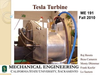
- 1. Tesla Turbine ME 191 Fall 2010 Raj Basuta Beau Camaren Monty Dhimmar Frank Keefer Lo Saetern
- 2. Review the Tesla Turbine What is it? Turbine with flat, encased, co-rotating disks Extract energy from a fluid inserted tangentially Converts kinetic energy of fluid into mechanical energy of a rotating shaft through frictional energy transfer Why study it? To explore why such a potentially green energy conversion device has not made it to wide-spread industrial use today
- 4. Early Difficulties Flatness of disks was out of specification with 10 gage 1018 steel sheet being warped Tested 13 disks with dial indicator after having fabricated 20, and selected the best 10 for use Using a lathe, flats were machined on the jam nuts to match the lightly ground and polished disks all relative to shaft to maintain uniformity of system
- 5. Test Setup
- 6. Sensor Calibration Speed Sensor – Honeywell 3010AN Pressure Diff. Transducer – PX771100WDI Inlet Pressure Transducer – Honeywell Thermocouples – J Type from Omega
- 7. Flow Testing Used campus energy lab, compressor, and 9 ft3 tank charged to 200 psi and discharged into the turbine An orifice plate, thermocouples, and pressure transducers with Labtech software, were used to find inches of water After running calculations to convert, a flow of approximately 5 lb/minute was found
- 8. RPM Testing With the same tank and compressor set-up and charging to 300 psi and discharged into the turbine over a span of about 4.5 minutes A speed sensor was mounted on the turbine endplate to count the 60 teeth of a sprocket fixed to the shaft as it spun Maximum RPM was calculated as 4000 http://www.youtube.com/watch?v=4zxp_ML1kO0
- 9. Power Testing Could not use Dyno, so Power found through Kinetic Energy calculations using inertia of system and LabView LabView sensors: RPM Time Pressure Inlet and Outlet Temp Flow Rate
- 10. Power Testing Using this information the fallowing graph was produced
- 13. Power Testing Equations for power Equations for Efficiency
- 14. Fin Thank You Mechanical Engineering Department Faculty and Students, your efforts are truly appreciated Questions?
Notes de l'éditeur
- Beau
- Beau
- Beau
- Monty
- Monty - Basics of the test set up. National instruments data acquisition system cDAQ-9172 plus national instruments modules that measured the outputs of the sensors.
- MontySensorsRPM- Honeywell Speed sensor Electro 3010anThe rpm sensor works by the action of a magnet and the teeth of a gear passing by. The movement of the magnet causes a sine wave output of the sensor who’s frequency is a measure of the number of teeth passing by. The gear we had has 60 teeth on it so it automatically provided an output of RPM.Inlet Pressure Transducer OmegaPressure difference transducer Px771-100wdiThermocouples J-type omega
- Lo - This was the Preliminary testing to find the flow rate of the air supply of the system.
- Raj - This was the preliminary test results for the RPM of the systemThis test came after a disappointing visual test conducted as soon as assembly was complete.The primary reason for the early disappointment was increased friction on the bearings due to extra precautionary measures, especially resulting from the bearing stop.
- Raj- This slide shows the sensors we used and that they were hooked to lab view. This slide shows also shows general test.
- Lo - This graph shows that the Rpm increases as the pressure was released from the air tank.When the air supply was shut off after the max rpm was reached the rpm linearly decreased which shows that their isn’t much air drag in our system.
- Lo
- Frank
- Frank
- Raj