PLC application
•
0 j'aime•1,078 vues

plc, PLC Applications, Programmable Logic Controllers, Programmable, Logic, Controllers, PROGRAMMING, gates, COUNTERS, Timers,LOGIC CIRCUITS, INTERNAL RELAYS, ARITHMETIC FUNCTIONS, Application, Data Types and Addressing,

Recommandé
Contenu connexe
En vedette
En vedette (20)
Similaire à PLC application
Similaire à PLC application (20)
Plus de Ameen San
Plus de Ameen San (16)
Dernier
Dernier (20)
PLC application
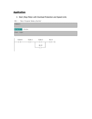
- 1. Application 1- Start /Stop Motor with Overload Protection and Speed Limit.
- 2. 2- The analog input address can be PIW752, but for simulation purposes we use MW98 instead. 3- If there is an analog input, its range will be from 0V to 10V, this corresponds to 27648 (The value 27648 has simply been selected as the maximum normal range value of any analog signal transferred to the CPU by a Siemens analog module. This numerical value is independent of the resolution of the particular analog module used (this is a way to standardize all scaling of analog readings in the processor). For uni-polar data, this would mean 0 to 27648 represents full range; above 27648, over range, below 0, under range). 4- We want to convert the range (0 – 27648 to 0 – 100) to represent the speed in a sensible range. 5- First we convert the Integer to D-Integer since there is no direct conversion from Integer into Real. 6- We divide by 27648 then multiply by 100.
- 3. 7- Now we come to the supervision stage, we want to monitor the motor if it exceeds 70% of its rated speed. If it exceeds 70%, the marker M1.1 will be ON. By this way the motor Q124.0 will be OFF.
- 4. 8- Finally, we want to put a set point to the motor (ex. 60), first we multiply the speed percentage (MD224) into 27648, and then divide by 100 then use round function. Note that MD220 consists of MW220 and MW222m but MW222 contains the required INTEGER part. Now PQW752 corresponds to the range 0 to 27648 or 0 to 10V.
- 5. To monitor the program we construct a variable table. In this case the motor will exceed the 70% limit, so the motor will not run. In this case the motor will not exceed the 70% limit, so the motor can run according to the set value. Its speed will be 50% of its rated value. Note that the analog output is 50% of the full range (13824 of 27648).