Boiler, Steam Trapes, Insulation and Steam Distribution System
•Télécharger en tant que PPTX, PDF•
8 j'aime•3,538 vues

For all Engineering peoples

Recommandé
Contenu connexe
Tendances
Tendances (20)
En vedette
Similaire à Boiler, Steam Trapes, Insulation and Steam Distribution System
Similaire à Boiler, Steam Trapes, Insulation and Steam Distribution System (20)
Dernier
Dernier (20)
Boiler, Steam Trapes, Insulation and Steam Distribution System
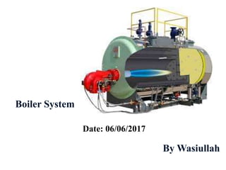
- 1. Boiler System Date: 06/06/2017 By Wasiullah
- 2. BOILER: A boiler is defined as "a closed vessel in which water or other liquid is heated, steam or vapor is generated, steam is superheated, or any combination , under pressure or vacuum, for use external to itself, by the direct application of energy from the combustion of fuels, from electricity or nuclear energy." Types of Boiler: 1) Fire Tube Boiler 2) Water Boiler
- 3. Fire Tube Boiler: The fire tube boiler design uses tubes to direct the hot gases from the combustion process through the boiler to a safe point of discharge. The tubes are submerged in the boiler water and transfer the heat from the hot gases into the water. Types of fire-tube boiler • Cornish boiler. • Lancashire boiler. • Scotch marine boiler. • Locomotive boiler. • Vertical fire-tube boiler. • Horizontal return tubular boiler. • Immersion fired boiler.
- 4. • Cornish boiler : Cornish boiler is a simple horizontal boiler which belong to the shell and tube class of boilers. Cornish boiler is much like the Lancashire boiler. Cornish boiler has the ability to produce steam at the rate of 1350 kg/hr and can take the maximum pressure of about 12 bar. Dimensions of the Cornish boiler shell is 4 m to 7 m in length and 1.2 m to 1.8 m in diameter. • Lancashire boiler: The Lancashire boiler is similar to the Cornish, but has two large flues containing the fires instead of one. It is generally considered to be the invention of William Fairbairn in 1844, although his patent was for the method of firing the furnaces alternately, so as to reduce smoke, rather than the boiler itself.
- 5. • Scotch Marine Boiler: The Scotch Marine Boiler is a fire-tube boiler, in that hot flue gases pass through tubes set within a tank of water. The general layout is that of a squat horizontal cylinder. One or more large cylindrical furnaces are in the lower part of the boiler shell. Above this is a large number of small-diameter fire-tubes. • Locomotive boiler: Locomotive boiler is the horizontal fire tube boiler in which hot gases pass through the tubes and water surrounds them. Transferred heat from the gases to water and then converted into steam. It may also be used as a stationary boiler.
- 6. • Vertical fire-tube boiler : A vertical fire-tube boiler or vertical multitubular boiler is a vertical boiler where the heating surface is composed of multiple small fire-tubes, arranged vertically. These boilers were not common, owing to drawbacks with excessive wear in service. The more common form of vertical boiler, which was very similar in external appearance, instead used a single flue and water-filled cross-tubes. • Horizontal return tubular boiler: A fire-tube boiler is a type of boiler in which hot gases from a fire pass through one or (many) more tubes running through a sealed container of water. The heat of the gases is transferred through the walls of the tubes by thermal conduction, heating the water and ultimately creating steam.
- 7. • The immersion fired boiler: The immersion fired boiler is a single-pass fire-tube boiler that was developed by Sellers Engineering in the 1940s. It has only firetubes, functioning as a furnace and combustion chamber also, with multiple burner nozzles injecting premixed air and natural gas under pressure. It claims reduced thermal stresses, and lacks refractory brickwork completely due to its construction
- 8. Water Tube Boiler: The water tube boiler design uses tubes to direct the boiler water through the hot gases from the combustion process, allowing the hot gases to transfer its heat through the tube wall into the water. The boiler water flows by convection from the lower drum to the upper drum. Types of Water Tube Boiler: • Horizontal Straight Tube Boiler. • Bent Tube Boiler. • Cyclone Fired Boiler
- 9. Burner is a mechanical device that burns a gas or liquid fuel into a flame in a controlled manner. Energy Efficient Burner: An efficient burner provides the proper air-to-fuel mixture throughout the full range of firing rates, without constant adjustment. Many burners with complex linkage designs do not hold their air-to-fuel settings over time. Often, they are adjusted to provide high excess air levels to compensate for inconsistencies in the burner performance. BURNER
- 10. Energy Saving Due to Installation of an Energy Efficient Burner Burner Combustion Efficiency Improvement % Annual Energy Savings (MMBtu/year) Annual Savings ($) 1 6,250 28,125 2 12,345 55,550 3 18,290 82,305 Cost Savings = Fuel Consumption * Fuel Price * (1-E1/E2) If the installed cost is $50,000 for a new burner that provides an efficiency improvement of 2%, the simple payback on Investment is: Simple Payback = $50,000 ÷ $55,550/ year = 0.9 Years Example; Even a small Improvement in burner efficiency can provide significant savings. Consider a 50,000 pound per hour process boiler with a combustion efficiency of 79% (E1). The Boiler annually consumes 500,000 million British thermal units(MMBtu) of natural gas. At a price of $4.50/MMBtu, the annual fuel cost is $2.25million. What are the saving from installing an energy efficient burner that improves combustion efficiency by 1%, 2%, or 3 %.
- 11. • Perform burner maintenance and tune your boiler. • Conduct combustion-efficiency tests at full- and part-load conditions. • If the excess O2 exceeds 3%, or combustion efficiency values are low, consider modernizing the fuel/air control system to include solid-state sensors and controls without linkage. Also consider installing improved process controls, an oxygen trim system, or a new energy-efficient burner. • A new energy-efficient burner should also be considered if repair costs become excessive, reliability becomes an issue, energy savings are guaranteed, and/or utility energy-conservation rebates are available. • Install a smaller burner on a boiler that is oversized relative to its steam load. SUGGESTED ACTIONS
- 13. • Air Properties: For a burner originally adjusted to 15 % air, changes in combustion air temperature and barometric pressure cause the following in excess air: Expressed as a percent of the stoichiometric air required.
- 15. PASSES OF BOILERS Three-pass firetube boiler: A 3-pass firetube boiler design consists of three sets of horizontal tubes, with the stack outlet located on the rear of the boiler. A downdraft design keeps the cooler water from having an effect on the hot surfaces within the boiler. 3 pass firetube boilers offer: • maximized heat transfer • minimal refractory • high steam/water storage • effective handling of wide load demands
- 16. Four-pass boiler: A four-pass boiler design consists of four sets of horizontal tubes, with the stack outlet at the front of the vessel. A downdraft design keeps the cooler water from having an effect on the hot surfaces within the boiler. 4-pass boilers leverage natural draft operation which allows cool water to contact the hottest part of the boiler. 4 pass firetube boilers offer: • maximized heat transfer • minimal refractory • high steam/water storage • effective handling of wide load demands
- 17. BOILER PERFORMANCE TEST Performance of the boiler, like efficiency and evaporation ratio reduces with time, due to poor combustion, heat transfer fouling and poor operation and maintenance. Deterioration of fuel quality and water quality also leads to poor performance of boiler. Efficiency testing helps us to find out how far the boiler efficiency drifts away from the best efficiency. • To find out the efficiency of the boiler • To find out the Evaporation ratio The purpose of the performance test is to determine actual performance and efficiency of the boiler and compare it with design values or norms. It is an indicator for tracking day-to-day and season- to-season variations in boiler efficiency and energy efficiency improvements 1. Boiler Efficiency = Heat Output/Heat Input*100 = Heat In Steam Output(kCals)/Heat in fuel Input(kCals)*100 2. Evaporation Ratio = Quantity of Steam Generation/Quantity of Fuel Consumption
- 19. Heat recovery equipment is available to preheat feed water entering the boiler (economizer) and to capture Btu’s lost through boiler blowdown (blowdown heat recovery or flash tank heat exchangers). Such equipment is normally used on installations where boiler size, operating pressures or the amount of water make-up justify the economics for the purchase and installation costs (normally units exceeding 100 hp and operating at 100 psi or more). Maintenance costs also must be considered before a decision is made for their installation. HEAT RECOVERY EQUIPMENT
- 20. Economizers are bent, finned-tube heat exchangers. They are available in rectangular or cylindrical styles. The type of boiler and the overall boiler room layout may dictate which style is utilized. The products of combustion leaving the boiler flow through the economizer, over the finned tubes, transferring its heat or Btu’s to the boiler feed water. The efficiency of the overall system can be increased By 2% to 4%, depending on fuel being burned, boiler size, and operating conditions. ECONOMIZERS
- 21. There are several methods and equipment used in blowdown heat recovery. In most cases, the systems are used on continuous or surface blowdown to control the Total Dissolved Solids (TDS) in the boiler water. Blowdown heat recovery equipment is used for automatic control of the continuous blowdown, based on water make-up and cools the continuous blowdown to a point where it can be safely dumped to the sewer system. It transfers heat or Btu’s to the make-up water, thus raising the temperature of the make- up water before it enters the deaerator or boiler feed system. BLOWDOWN EQUIPMENT
- 22. An additional piece of equipment, the blowdown separator , can be installed for bottom blowdown. The blowdown separator reduces the temperature of the bottom blowdown water to a temperature that would be safe for the sewer system. However, because of the erratic flow of bottom blowdown, there is little benefit to use a blowdown separator as a means to raise the temperature of make-up water prior to entering the deaerator or boiler feed system. BLOWDOWN SEPARATOR
- 23. Another system uses the addition of a flash tank heat exchanger. This system works on the same principle as the blowdown heat recovery system, however, it also provides the benefit of flash steam. This flash steam can be reused in the plant, such as being piped to a deaerator and mixed with the incoming steam in the deaerator. FLASH TANK HEAT EXCHANGER:
- 24. During daily operation of a plant, a sample cooler is normally required to draw samples of boiler water, so chemical tests can be performed. The boiler water, however, is above the temperature that test equipment can handle. In most cases, the situation is resolved with the installation of a sample cooler. SAMPLE COOLER
- 25. Boiler feed water usually contains two harmful dissolved gases: Oxygen and Carbon Dioxide. If the dissolved gases are not removed before entering the boiler, they will be liberated by heat and may cause severe corrosion in the boiler, steam lines, condensate lines, and heat transfer equipment, which can prove to be very costly. The dissolved oxygen and carbon dioxide can be removed with chemicals. Depending on the overall system, it may not be practical to chemically remove the dissolved oxygen and carbon dioxide from the feed water. In these cases, a deaerator should be installed. Because the deaerator mechanically removes dissolved oxygen and carbon dioxide, the amount of chemicals required could be reduced. BOILER FEEDWATER EQUIPMENT
- 26. The deaerator is a pressurized American Society of Mechanical Engineers (ASME) tank and may be the largest piece of auxiliary equipment in the boiler room. A deaerator is designed to heat water to the temperature of saturated steam at the pressure within the deaerator. A deaerator provides an effective means for recovery of heat from exhaust or flash steam, provides a location for returning condensate and accepts condensate first to reduce excessive make-up water. There are three types of deaerators available. The tray type is normally used in large utility plants. DEAERATORS
- 27. If plant conditions do not warrant the use of a deaerator, in most cases, a Packaged Feed System is used. The packaged feed system is an atmospheric tank that can heat feed water to a maximum of 210°F. Because they are atmospheric tanks, they are equipped with an epoxy lining or made from galvanized steel. The packaged feed system heats the feed water and reduces the amount of dissolved oxygen and carbon dioxide in the feed water. There are many additional pieces of equipment available to remove impurities in the make-up water before it enters the boiler and system. The type of equipment required is determined by a water analysis. This equipment can be classified as pre-treatment equipment. FEED SYSTEMS
- 28. Filters are available to remove free chlorine, some dissolved organics and sediment. They can also remove suspended solids, colloidal matter, sand and iron. There are carbon filters, multilayered filters, sand or iron filters. There can be lined tanks, American Society of Mechanical Engineers (ASME) code tanks and automatic operation based on a time clock, pressure differential switch or water meter. They can protect such items as water softeners, dealkalizers, and reverse osmosis equipment, etc. PRE-TREATMENT EQUIPMENT:
- 29. A surge tank could be used under the following conditions: If there are intermittent peak loads of condensate that can exceed the surge capacity of the deaerator - varying pressures or temperatures in condensate – gravity or pumped condensate that have insufficient pressure to enter the deaerator on their own. Surge tanks are atmospheric and accept condensate and make-up water before it goes to the deaerator. Surge tanks can be lined with an epoxy coating to prevent corrosion. The condensate and make- up water mix into a blend temperature as determined by the percentage of each. SURGE TANK
- 30. The Flame Safeguard or Programming Control on boilers are designed to ensure that the start-up of the burner follows a definite timed sequence of operation. In addition to the sequence of operation and after the flame has been established, the Flame Safeguard monitors the flame and sets the firing rate of the burner, as determined by the boiler firing rate controls. They also monitor, through the boiler controls, items such as boiler pressure or temperature, fuel pressure or temperature and they provide for normal shut down of the burner if the load demand is satisfied, or shut down and alarm if there is a safety shut down condition. The Flame Safeguards or Programming Control installed on a boiler can be classified into three categories: o Electro Mechanical o Solid State Electronic o Micro Processor FLAME SAFEGUARD EQUIPMENT
- 31. The electro mechanical controls have been used from around 1950 until 1984. Solid state electronic controls were introduced in 1984. This type of control provides for more alarm or monitoring functions than the electro mechanical controls. The micro processor controls introduced in 1989 not only provide the functions as the other controls, but also have the ability to send information to computers and work in conjunction with some energy management systems. The micro processor type of controls are standardly furnished on some of today’s modern boilers. Solid state electronic controlsElectro mechanical controls
- 32. After the initial inspection is completed, the new boiler is ready for startup. Startup can be the most critical period in the life of the boiler. 1. Steam piping, blow off and blowdown lines, etc. must be inspected and ready for operation. All piping must be inspected for adequate support and expansion provisions. 2. All fuel supply lines must be checked for tightness and leaks. Strainers are most important to the safe operation of gas and/or oil fired units. 3. Electrical power lines to the boiler/burner unit are connected and the voltage required is verified. 4. Hydrostatic test has been completed. 5. Any walkways, platforms, stairs, and/or ladders, etc., that are needed to permit proper access to the boiler/burner, are installed and ready for use. BOILER STARTUP
- 33. Before the boiler is permitted to go on the line, all of the safety controls should be checked to make sure they are all operating properly. Flame Safeguard: The purpose of the flame safeguard control is to monitor the burner start up sequence, the main flame and control the firing rate during normal operation. Following is a brief step-by-step: 1. The burner switch is turned on or the operating limit pressure (or temperature) control closes. If all required limit controls are satisfied, the blower motor starts and the automatic sequence begins. 2. The programmer actuates the modulating motor and drives it to high fire position and purges the boiler for a predetermined period of time. 3. The programmer drives, modulating motor and burner linkage back to low fire position. BOILER CONTROLS
- 34. 4. The ignition transformer is energized and the pilot solenoid valves are opened. The pilot must light. 5. Trial for ignition period. 6. If the pilot flame is proven, the programmer, after a timed interval, energizes the main flame fuel valve(s) and trial for main flame is started, at minimum fuel rate. 7. After a timed period, the main flame has to be established. If this is completed, the programmer extinguishes the pilot and then continues to monitor the main flame. 8. The programmer continues to monitor the main flame while the burner continues to automatically modulate (if the burner is capable of full modulation) on an increasing or decreasing firing rate to satisfy the load demand. 9. The programmer cycles to off position and is now ready for restart upon demand.
- 35. 1. Know your equipment. 2. Maintain complete records. 3. Establish a regular boiler inspection schedule. The schedule should include daily, weekly, monthly, semi-annual and annual inspections or activities. 4. Establish and use boiler log sheets. Log sheets should be tailored to your equipment. 5. Establish and keep written operating procedures updated. 6. Good housekeeping is a must. 7. Keep electrical equipment clean. BOILER ROOM CARE
- 36. 1. Check water level. Ensure there is water in the gauge glass every time you enter the boiler room. 2. Blow down boiler. Blow down the boiler in accordance with the recommendation of your feedwater consultant. 3. Blow down the water level controls to purge the float bowl of possible sediment accumulation. Operating conditions will dictate frequency of this check. 4. Check combustion visually. Look at the flame to see if something has changed. 5. Treat water according to the established program. Add chemicals and take tests as outlined by your chemical feedwater consultant. 6. Record boiler operating pressure or temperature. 7. Record feedwater pressure and temperature. 8. Record stack temperature. Changes in stack temperatures could indicate the boiler is sooting, scaling or there is a problem with baffles or refractory. DAILY MAINTENANCE
- 37. 9. Record oil pressure and temperature. 10. Record oil atomizing pressure. Changes in pressure could have an effect on combustion in the boiler. 11. Record gas pressure. Changes in pressure could have an effect on combustion in the boiler and indicate a problem in the gas delivery system. 12. Check general boiler/burner operation. Maintaining top efficiency is the simple and basic reason for having operating personnel. Is anything different than it was the day before? If so, why? 13. Record boiler water supply and return temperatures. On hot water boilers, record these temperatures to assist in detecting system changes. 14. Record makeup water usage. Excessive makeup water could be an indication of system problems in both steam and hot water systems. 15. Check auxiliary equipment.
- 38. 1. Check for tight closing of fuel valves. 2. Check fuel and air linkages. 3. Check indicating lights and alarms. 4. Check operating and limit controls. 5. Check safety and interlock controls. 6. Check operation of water level controls. 7. Check for leaks, noise, vibration, unusual conditions, etc. Checking for these items is a cost effective way to detect system operational changes. Small problems can be corrected before they become large problems. 8. Check operation of all motors. 9. Check lubricating levels. 10. Check the flame scanner assembly. 11. Check packing glands on all pumps and metering devices. 12. Check gauge glass. Ensure there are no cracks or etching in the glass or leakage around the packing. WEEKLY MAINTENANCE
- 39. 1. Inspect burner operation. 2. Analyze combustion. 3. Check cams. Inspect the cam springs for scoring, tightness of set screws, free movement, alignment of cam followers and other related parts. 4. Check for flue gas leaks. 5. Inspect for hot spots. Inspect the boiler to ensure no hot spots are developing on the outside of the boiler. 6. Review boiler blowdown to determine that a waste of treated water is not occurring. 7. Check all combustion air supply inlets to the boiler room and burner to ensure sufficient air is being supplied. 8. Check all filter elements. Clean or replace as needed 9. Check the fuel system to make certain that strainers, vacuum gauges, pressure gauges and pumps are properly cared for. 10. Check all belt drives for possible failure. MONTHLY MAINTENANCE
- 40. 1. Clean low water cutoff . Remove the head assembly or probes and inspect and clean out any sediment or contamination in the column or piping. 2. Check oil preheaters by removing the heating element and inspect for sludge or scale. 3. Repair refractory. Immediately upon opening the fireside areas, give the refractories an inspection and start repairs as soon as possible. 4. Clean oil pump strainer and filter. 5. Check pump coupling alignment. 6. Reset Combustion. The entire combustion process should be carefully checked, O2 readings taken and necessary burner adjustments made. 7. Inspect mercury switches. Inspect mercury switches for contamination, loss of mercury, and cracked or broken wires. Replace if any of these conditions are found. SEMI-ANNUAL MAINTENANCE
- 41. 1. Clean fireside surfaces by brush or use a powerful vacuum cleaner to remove soot. 2. Clean breeching. Inspect breeching and stack and remove any soot build up. 3. Clean waterside surfaces. Remove all hand hole and manway plates, inspection plugs from water column tees and crosses and float assemblies from water columns. 4. Check fluid levels on all hydraulic valves. If any leakage is apparent, take positive corrective action immediately. 5. Check gauge glass for possible replacement. If internal erosion at water level is noted, replace with new glass and gaskets. 6. Remove and recondition safety valves. Have them reconditioned by an authorized safety valve facility. 7. If oil fuels are used, check on the condition of the fuel pump. Fuel pumps wear out and the annual inspection time is the opportune time to rebuild or replace them. ANNUAL MAINTENANCE
- 42. 9. Boiler feed pumps. Strainers should be reconditioned. 10. Condensate receivers should be emptied and washed out. Make an internal inspection, if possible. 11. Chemical feed systems should be completely emptied, flushed and reconditioned. Metering valves or pumps should be reconditioned at this time. 12. Tighten all electrical terminals. All terminals should be checked for tightness, particularly on starters and movable relays. 13. Check linkages. Check to ensure the linkage ball connectors have not worn out. Worn connectors can cause inconstancy in the linkage movement and result in unrepeatable excess air levels in the combustion process.
- 43. 1. The boiler room is for the boiler. The boiler room should not be considered an all-purpose storage area. The burner requires proper air circulation in order to prevent incomplete fuel combustion and production of carbon monoxide. Therefore, keep the boiler room clean and clear of all unnecessary items.1. 2. Knowledge is powerful, as are boilers. Ensure all personnel who operate or maintain the boiler room are properly trained on all equipment, controls, safety devices, and up-to-date operating procedures.1. 3. Look for potential problems. Before startup, ensure the boiler room is free of all possibly dangerous situations, such as flammable materials or mechanical or physical damage to the boiler or related equipment. Clear intakes and exhaust vents; check for deterioration and possible leaks. BOILER ROOM GUIDELINES
- 44. 4. Observe new equipment. Monitor all new equipment closely until safety and efficiency are demonstrated. 4. Develop a maintenance schedule. Use boiler operating log sheets, maintenance records, and manufacturers’ recommendations to establish a preventive maintenance schedule based on operating conditions, as well as on past maintenance, repairs, and replacements performed on the equipment. 6. Inspection matters. Ensure a thorough inspection by a properly qualified inspector, such as one who holds a National Board commission. 7. Reinspection matters, too. After any extensive repair or new installation of equipment, make sure a qualified boiler inspector reexamines the entire system.
- 45. 8. Create thorough checklists. Establish a checklist for proper startup and shutdown of boilers and all related equipment according to manufacturers’ recommendations. 9. Don’t overlook automated systems. Observe equipment extensively before allowing an automated operation system to be used with minimal supervision. 10. Keep safety at the forefront. Establish a periodic preventive maintenance and safety testing program.
- 46. STEAM TRAPES
- 47. 1.) Points about the steam trap a. Mechanical steam trap b. (On/Off Operation) c. Test point – downstream of the discharge orifice 2.) Visual inspection a. Steam trap should be level to the eye b. Check flow arrow to insure steam trap is installed correctly 3.) Temperature measurement a. Take temperatures before and after steam trap b. Temperatures below 212°F or 100°C, steam trap is not in operation c. Take temperature at the process inlet. Temperatures at the process inlet and the steam trap inlet will be relatively close. 4.) Off position during operation a. Ultrasound level should be low or zero on the ultrasound meter b. Long off periods can cause “loss of prime”
- 48. 5.) Discharge Operation (discharging condensate) a. When the inverted bucket drops due to the loss of buoyancy, this will bring the valve away from the discharge orifice. This action will allow the steam trap to discharge the condensate. b. The ultrasound indicator will rise due to the increase in ultrasound from the discharge cycle. The ultrasound will stay high or full scale until condensate is discharged from the steam trap. The ultrasound level (meter) should deflect more than 30% of scale. c. When condensate is completely discharged, the inverted bucket will rise, due to buoyancy, and bring the valve in contact with the discharge orifice .The steam trap is now in the off position. The ultrasound level should be at zero or minimum.
- 49. d. Ultrasound level should proceed to full or high ultrasound level during the discharge cycle and return to minimum scale reading or zero after the discharge is complete. e. Condensate will crackle and steam will whistle during testing with the ultrasound equipment, therefore during the cycling there will be a crackling + whistling sound during the discharge cycle (steam and condensate passing through the orifice of the steam trap). f. The steam trap should stay in the off position for a least 15 seconds before cycling (less than 15 seconds if the steam trap is undersized) g. Discharge – ultrasound meter should increase the ultrasound level. h. The steam trap has a fast on/off operation. 6.) Light Condensate Load Operation a. Ultrasound levels will cycle on and off at low ultrasound levels. This is an indication of low condensate flows.
- 50. 7.) Failure Modes a. Leaking steam Steam trap valve wear or linkage will cause the steam trap to leak steam. The following are indicators of leaking steam: • Ultrasound meter does not return to zero or baseline after condensate discharge cycle. • Ultrasound levels are continuous off base line and there is not distinct cycle/no cycle operation.
- 51. b. Blowing steam Steam trap valve or linkage failure or over sizing (loss of prime) will cause the steam trap to blow steam directly through the steam trap. The following are indicators of leaking steam: • Ultrasound meter is at full scale. • Hearing a dominant whistling sound and no crackling.
- 53. STEAM SYSTEMS IN INDUSTRY AND OTHER SECTORS • Steam can be used for heating, drying, moistening and sterilization of products in industry and other fields • Steam has advantages in effective heat transfer, indirect or direct heating and hygienic. • Special attention shall be given in productivity of steam production (exhaust gas and blowout losses), distribution networks and steam users. • Water treatment and high maintenance needs may increase operating costs.
- 54. STEAM PRODUCTION • Steam can be produced by steam boilers and steam generators. • Key factors in economic steam production o boiler plant o continuous consumption monitoring o skilled personnel • Considerations in boilers o boiler capacity meets steam requirements o meters are in good condition o out-blow is not excessive o economizer is in operation o heat transfer surfaces are clean o boiler has no air leakages o boiler insulation is in good condition
- 55. STEAM NETWORKS • Steam use can be either direct or indirect, but the used energy amount is the same, but heat losses may differ. • In direct use the valuable condensing water return shall be checked regularly • Superheated steam has lower heat transfer coefficient than saturated steam • Moist steam stress equipment more than dry steam • Air mixed in steam reduces the heat transfer coefficient
- 56. LEAKAGES • Leaks in steam systems o waste continuously energy (24/7) o reduce network pressure and energy flow o waste valuable condense water (treated water) o reduce work safety (blasts) • To be checked visually or with ultrasonic detector o safety valves, steam traps, orifice connectors, gate valves, unattended pipe-tunnels o leakage inspections shall be made at least twice per year
- 57. PIPE AND EQUIPMENT INSULATION • Pipes, flanges, equipment and valves shall be insulated because of heat losses and working safety • Condense pipes always insulated, except condense valves • Wet insulation causes energy waste and outside corrosion • Un-insulated DN 200 valve may have up to 200 C temperature and 5 kW continuous heat loss
- 58. CONDENSE RETURN • Condense return is important in indirect steam use. Condense traps are important. • Precise condense return causes: o good utilization of condense heat content o reduction in make-up water needs • Closure of open condense tank causes o reduction in heat loss o reduction in tank corrosion • Condense tank should be blanketed from oxygen entry by steam etc
- 59. FAILURES IN CONDENSE TRAPS • Condense return rate shall be monitored and maximized • Fault trap causes steam-condense mix in condense pipe leading to increased temperate and backpressure, increased steam consumption, higher condense and high feed water pumping costs • Faults in condense traps should be seek by listening (man / machine) and by temperature metering (every 2 to 4 months)
- 60. UTILIZATION OF BLOWOUT STEAM • Benefits of blowout o Reduced steam consumption o Lost blowout steam reduces o Capacity of condensing network increases • Utilization of blowout steam o Blowout steam usage in low pressure systems o Preheating of combustion air, compressed air and rooms o Heating of sub-cooled condense or preheating of process-water in condense tank
- 61. ECONOMICAL USE OF STEAM • Steam pressure o Is defined by required temperature /pressure level o It is important that temperature/pressure meets the user requirements o It is important that pressure fluctuation is as small as possible o Steam networks can be divided by pressure reduction valves to different pressure subnets
- 62. EQUIPMENT CONSIDERATIONS • Very important that process automation works properly • Steam network and equipment shall be started slowly • Steam heated equipment shall have thermal insulation • Open liquid surfaces shall be covered against evaporation • Bypass valves shall be kept closed and watertight • Minimization of steam pressure, finally replacing steam with hot water • Drying first by mechanical water removal, then steam-drying and avoid over-drying • Avoid unnecessary stand by use of steam systems
- 63. Install air-atomizing and low-nitrogen-oxide (NOx) burners for oil- fired boiler systems. Install automatic boiler blow-down control. Conduct flue gas Test of boilers. Install an automatic flue damper to close the flue when it is not firing. Install tabulators to improve heat transfer efficiency in older fire tube boilers. Install low-excess air burners. Install condensing economizers. Install electric ignitions instead of pilot lights. Install an automatic combustion control system to monitor the combustion of exit gases and adjust the fuel-air ratio to reduce excess combustion air. Install isolation valves to isolate off-line boilers. ENERGY CONSERVATION MEASURES FOR BOILERS AND FIRED SYSTEMS
- 64. Maintain insulation on the heat distribution system. Replace insulation after system repair, and repair damaged insulation. Provide proper water treatment to reduce fouling. Replace central plant with distributed satellite systems. Downsize boilers with optimum burner size and forced draft (FD) fans. Operate boilers at their peak efficiency; shut down large boilers during summer and use smaller boilers. Install expansion tanks on hot-water systems that are properly sized for the system. Employ heat recovery through desuperheating. Preheat combustion air, feed water, or fuel oil with reclaimed waste heat from boiler blowdown and/or flue gases. Install automatic controls to treat boiler makeup water. Check steam trap sizes to verify they are adequately sized to provide proper condensate removal.
- 65. Adjust boilers and air-conditioner controls so that boilers do not fire and compressors do not start at the same time but satisfy demand. Clean boiler surfaces regularly to reduce scale and deposit, which will improve heat transfer. Replace noncondensing boilers with condensing boilers (15%– 20% higher efficiency when compared to new noncondensing boilers). Prevent dumping steam condensate to drain. Survey and fix steam/hot-water/condensate leaks and failed steam traps. Convert steam system to low-temperature sliding temperature hot-water system. Install complementing steam boilers where needed. Improve boiler insulation. It is possible to use new materials that insulate better and have lower heat capacity.
- 66. Boiler Horse Power (HP): BHP = (Lb/hr) * FE/34.5 Where Lb/hr is pounds of steam per hour and FE is the factor of evaporation. Cycle of Concentration of Boiler Water: CYC = Bch / FCh Where Bch is ppm water chlorides and FCh is ppm feed water chloride. Deferential Setting (lb): Delta s = p1 – p2 Where p1 is the cutout pressure and p2 is the cut in pressure. FORMULAS
- 67. Factor of Evaporation: FE = SH + LH / 970.3 Where SH is the sensible heat and LH is the latent heat. Force (lb): F = P/A Where P is pressure (psi) and A is area (ln^2). Horsepower (HP): HP = (d * t) / (t * 33000) Where d is distance, Fis force, and t is time. Inches of Mercury (in): lnHG = p / 0.491 Where p is pressure.
- 68. Percent of Blowdown: %BD = (PP - RP) / PP Where PR is popping pressure and RP is Reseat pressure Rate of Combustion (Btu/hr RC=H / (Vf * t) Where H is heat released (BTU), Vf is volume of furnace (ft^3), and t is time (hr). Return condensate Percentage in feedwater RC% = (MC - FC) / (MC – CC) Where MC is the makeup conductivity (μohms). Static Head pressure (lb) SHP = Bpr * 2.31 Where Bpr = boiler preesure (psi)
- 69. Steam: S = HP * 34.5 * t Where HP is Boiler horsepower and t is time (h). Temperature Conversions: F to C C = (F – 32) / 1.8 C to F F = (1.8 * C) + 32 Total Force (lb): TF = P * A Where P is pressure (psi) and A is the area of valve disc exposed to steam (sq.in.) Water Column (ln): WC = P / 0.03061 Where P is pressure (psi)